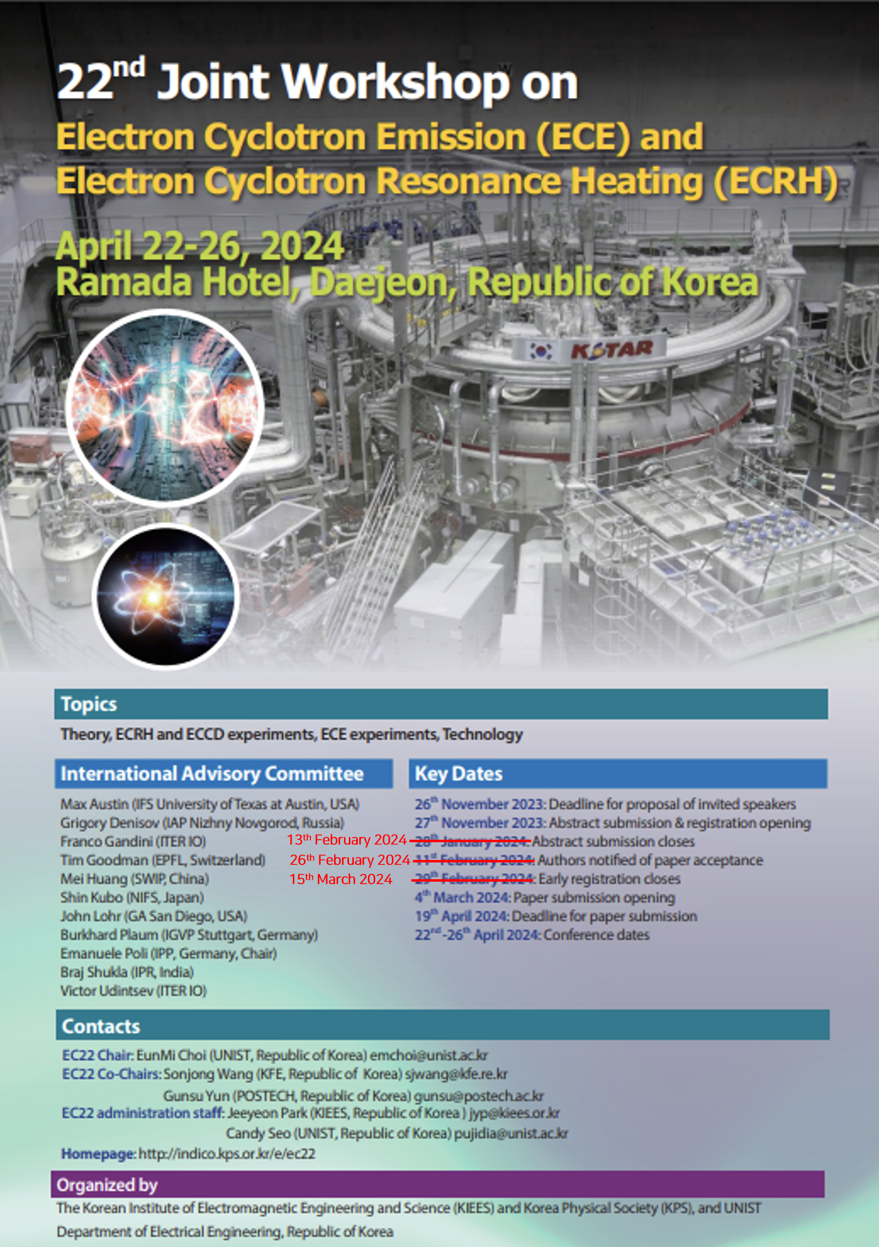
22nd joint workshop on electron cyclotron emission (ECE) and electron cyclotron resonance heating (ECRH)
Royal Ball Room
Ramada Hotel, Daejeon, Republic of Korea
The Submission of EPJ Web of Conference: https://indico.kps.or.kr/event/52/
The deadline of EPJ Web of Conference: June 24th, 2024
-
-
08:30
→
09:00
Registration 30m
-
09:00
→
09:30
Opening
-
09:00
Opening - [ Contratulatory Speech : KIEES President , PC Chair remark : Emanuele Poli , EC-22 Organizing Chair remark : Eunmi Choi ] 20m
dfads
-
09:00
-
09:30
→
10:40
Theory (Oral): ECRH Theory 1 // Chair: Emanuele Poli
-
09:30
Invited oral - Bodhi Biswas 30m
-
10:00
Kinetic full wave analysis of O-X-B mode conversion using integral form of dielectric tensor 20m
See attachments
Speaker: Prof. Atsushi Fukuyama (Kyoto University)
-
09:30
-
10:40
→
11:00
Coffee break 20m
-
11:00
→
12:10
Experiments (Oral): ECRH Experiments 1 // Chair: Mei Huang
-
11:00
Invited oral - Joerg Stober 30m
-
11:30
Progress of the electron cyclotron resonance heating system and the related experiments on J-TEXT 20m
In order to improve the ability of the J-TEXT tokamak which firstly only had the ohmic heating, we had begun to develop the electron cyclotron resonance heating (ECRH) system since 2017. The first ECRH system with the frequency of 105 GHz and the output power of 500 kW for 1s was successfully operated in 2019. This system is a traditional one which consists of a gyrotron from GYCOM, a transmission line with the length of about 30 m, a launcher with a elliptical mirror and a moveable flat mirror etc. Then, the second system with the same parameters was used for experiments in 2023 and the launcher was upgraded to inject the two beams. Up to now, the ECRH system has become one of the most important auxiliary system for the J-TEXT tokamak. Various experiments such as the assisted start-up, the control of the tearing mode, the electron thermal transport, the density limit etc. had been carried out on J-TEXT tokamak with the ECRH system.
Speaker: donghui Xia (Huazhong University of Science and Technology) -
11:50
Appearance and analysis of a reflecting coating damage 20m
Eight reflecting gratings are installed into the plasma facing wall of ASDEX Upgrade (AUG) in order to provide a controlled second pass through the plasma center in 140 GHz heating scenarios with reduced single pass absorption. Four of these gratings are machined out of W1.4901 steel and coated with tungsten to increase the reflectivity. During plasma operation three of the W1.4901 gratings worked very well, only one particular grating showed a strong correlation between the Gyrotron ON-time and an unusual increase in plasma radiation. After completion of the 2022 experimental campaign, this tile was taken out and carefully inspected.
Traces of local melting were observed and the tile was examined with a scanning electron microscope in order to determine the surface material composition. In the image of backscattered electrons it can be seen that tungsten is missing locally and along some of the ridges of the complex topology of the grating. Within these areas, the steel surface started to melt, which is in accordance with the assumption, that an intact tungsten coating indeed prevents the steel from melting.
The damaged tile is currently being replaced and we have implemented two measures in order to prevent such damage on the new tile. The first measure is to consequently finish all machining steps before the coating procedure. This is because a mechanical damage of the coating before the installation could not be ruled out. The second measure is to control and minimize the surface roughness after machining of the grating and before the coating procedure. It turned out that the roughness was up to 3 microns in the past, which seems to be too high for the desired quality of this particular coating. We have tested and developed an electro polishing procedure in order to decrease the surface roughness below 1 micron and keep the grating topology as precise as possible.Speaker: Martin Schubert (Max-Planck-Institut f. Plasmaphysik)
-
11:00
-
12:10
→
13:30
Lunch 1h 20m
-
13:30
→
14:40
Theory (Oral): ECRH Theory 2 // Chair: Lorenzo Figini
-
13:30
Invited oral - Benedetta Baiocchi 30m
-
14:00
Two-plasmon decay of microwaves in low temperature magnetized laboratory plasmas 20m
Evidence from past recent years show regions in the plasma, where 2nd harmonic X-mode (X2) waves are prone to non-linear wave interactions, known as parametric decay instabilities (PDI). These have been observed in tokamaks, such as ASDEX-U and TCV, and in the stellarator, Wendelstein 7-X. In this study, a numerical research of growth rates for PDI is carried out for linear plasma device parameters with constant magnetic field.
The PDI observed for X2 heating involves the coupling between the injected beam and natural modes of the plasma which enables for a transfer of energy between the waves. This results in a reduction in the efficiency of the ECRH scheme, where waves produced by PDI potentially alter the plasma behaviour as well, causing them to pose a threat to microwave-sensitive equipment. The observed signatures of PDI are predicted to occur due to a resonant two-plasmon decay (TPD) of an injected X2 wave into two, trapped upper-hybrid (UH) waves [1]. The trapping mechanism of the UH waves arises from non-monotonic density profiles caused by e.g. neoclassical tearing modes, edge localized modes or blobs. A linear conversion between X-mode waves and electron Bernstein waves (EBW) at UH layers, located on either side of the non-monotonic structure, will result in the trapping. The limited convection of the UH waves causes the instability to become absolute; the UH waves grow exponentially in time if the power threshold is exceeded. The growth of TPD heavily depend on cavity size of the plasma profile, wave lengths of the UH waves and the temperature of the plasma.
The numerical research carried out computes growth rates of the UH waves based on theoretical models, where Particle-in-cell simulations [2] are used in order to validate the results. The growth of the TPD instability is investigated within the following limits: Wavelengths of trapped UH waves being comparable to the size of the plasma, a lower temperature limit for the plasma, together with slow group velocities of the trapped waves. Lastly, the obtained results of growth rates are compared to experimental data.References
[1] S K Hansen et al., Plasma Physics and Controlled Fusion 63.9 (July 2021), p. 095002. doi: 10.1088/1361- 6587/ac0fd0
[2] T D Arber et al., Plasma Physics and Controlled Fusion 57.11 (Sept. 2015), p. 113001. doi: 10.1088/0741-3335/57/11/113001Speaker: Mr Johan Kølsen de Wit (Department of Physics, Technical University of Denmark, Fysikvej, DK-2800 Kgs. Lyngby, Denmark) -
14:20
Modelling of nonlinear collisionless electron cyclotron heating for the tokamak pre-ionization 20m
We report an analytical model for nonlinear collisionless electron cyclotron (EC) heating, accounting for electrons with non-zero initial perpendicular energy and high pitch angle under the 2nd harmonic, X-mode, perpendicular injection conditions with the help of the adiabatic Hamiltonian formulation [1]. During the tokamak pre-ionization stage, such electrons are expected to be present due to their low collisionality. However, the direct numerical integration of equations of motion for every resonant electron, especially at higher pitch angles [2], is too computationally expensive to implement it in breakdown transport simulations [3] and also complicated to apply for the 0D model such as burn-through modelling [4]. Therefore, analytic modelling is evidently necessary for designing the EC-injected startup scenarios in a tokamak. The proposed model provides an electron final energy, exhibiting good agreement with numerical integration results of equations of motion (see Figure 1 below) at a significantly reduced computational cost. We also report on total power absorption, assuming half transition probability for the Maxwellian distribution, and compare the results with numerical counterpart. This work is envisaged to contribute to sophisticated predictive modelling of EC pre-ionization and minimum required power for a successful plasma startup in ITER and beyond.
Speaker: Jinwoo Gwak (Seoul National University)
-
13:30
-
14:40
→
15:00
Coffee break 20m
-
15:00
→
17:30
KSTAR tour 2h 30m
-
17:30
→
18:00
Break 30m
-
18:00
→
20:00
Welcome Reception 2h
-
08:30
→
09:00
-
-
09:00
→
10:30
Experiments (Oral): ECRH Experiments 2 // Chair: Simon Freethy
-
09:00
Invited oral - Mei Huang 30m
-
09:30
Various Ohmic startup schemes with electron cyclotron heating via direct XB mode conversion in VEST 20m
In Spherical Torus (ST) with relatively low toroidal field, electron Bernstein wave (EBW) is known to be an efficient heating mechanism for high density plasmas without accessibility problem even at low frequency. Over-dense plasmas beyond L cut-off density was obtained via direct XB mode conversion from perpendicular low-field-side injection in Versatile Experiment Spherical Torus (VEST),[1] and they are utilized as an efficient pre-ionization in Trapped Particle Configuration for the development of a reliable and robust Ohmic start-up method in VEST and later in KSTAR.[2,3]
Relatively large wavelength of 2.45GHz at low toroidal field of the VEST was helpful for the microwave to transmit directly through the evanescent layer between R cut-off and upper hybrid resonance, allowing direct XB mode conversion instead of OXB mode conversion. Efficient XB mode conversion scheme was achieved in both short density scale length (Ln) and magnetic scale length (LB) regions positioned at outboard and inboard sides, respectively.
Pre-ionization scheme utilizing short LB region at the high field side of ST is more favorable to low loop voltage start-up by taking advantage of relatively strong electric field as well. With the enhanced pre-ionization a new merging start-up scheme can be developed by utilizing partial solenoids in VEST, where large stray field from the solenoid is unavoidable because of its geometry.
Solenoid-free start-up scenario is another scheme to be developed with the enhanced pre-ionization by utilizing low loop voltage from the evolution of equilibrium field of outer PF coils. Efficient XB mode conversion scheme utilizing short Ln region at the low field side of ST make this scenario feasible. Flux from external inductance change can be utilized when the plasma is started from outboard and moved inward. Various start-up schemes utilizing the improved EBW-assisted pre-ionization in VEST will be presented.References
[1] J.G. Jo, et al., Phys. Plasmas 24, 012103 (2017)
[2] Y. An, et al., Nucl. Fusion 57, 016001 (2017)
[3] J.W. Lee, et al., Nucl. Fusion 57, 126033 (2017)Speaker: Yong-Seok Hwang (Seoul National University) -
09:50
Analysis of Neoclassical Tearing Mode stabilization experiment by Electron Cyclotron Injection in KSTAR 20m
We report the neoclassical tearing mode (NTM) stabilization experimental results by injection of the electron cyclotron (EC) beam in KSTAR, and its analysis by calculating tearing stability index Δ′. In KSTAR #31747 experiment, the neoclassical tearing mode (NTM) is intentionally induced, and the KSTAR plasma control system (PCS) injects EC beam to stabilize the NTM. Here the EC is injected based on the minimum seeking control for the island growth rate [1,2,3], but unfortunately the EC deposition didn’t change enough. Consequently, the amplitude of the NTM instability significantly decreased towards the end of the experiment, followed by the recovery of plasma performance. To assess the NTM stabilization experiment from a stability perspective, we employed the STRIDE code [4], which can compute the Δ′ with toroidal geometry with a high speed. Utilizing the reconstructed equilibrium with magnetic diagnostics, we calculated the Δ′ for this experiment. As a result, we observed that the Δ′ is differed as the plasma’s state and the timing of EC injection. The result implies that calculation of Δ′ can be valuable in assessing the NTM stability, and that when we analyse the stability of NTM in experiment, careful consideration is needed.
Speaker: Mr MinSoo Cha (Department of Energy Systems Engineering, Seoul National University, Seoul, Korea) -
10:10
Influence of ECH on Magnetohydrodynamic (MHD) Instabilities Driven by Energetic Particles in Heliotron J 20m
Recent experiments in Heliotron J have delved into the response of energetic-particle-driven MHD
instabilities to electron cyclotron heating and current drive (ECH/ECCD) [1]. Specifically, we
conducted ECH modulation experiments to scrutinize mode stabilization and its underlying physical
mechanisms [2]. In our initial modulation experiment, the NBI power was modest at 90 kW in coinjection, while the second harmonic X mode ECH power was systematically modulated at 50 Hz.
As the ECH power gradually decreased to a certain threshold, it triggered the excitation of an
energetic-particle mode (EPM) with a frequency around 100 kHz [3]. In subsequent experiments,
we elevated the NBI power to approximately 100 kW in co-injection and 450 kW in counterinjection, leading to clearer excitation of the EPM and other modes. Our analysis focused on the
mode excitation's dependence on electron density and ECH power, revealing a time delay in ECH
modulation akin to our previous findings (see Fig. 1), indicating
a nuanced interplay between mode excitation and fast ion
confinement. ECH has the capability to alter ion, electron
Landau damping, radiation damping, and even continuous
spectrum damping. Conversely, variations in Te also impact
electron drag collisions, consequently influencing the
deceleration time. Furthermore, we explored the impact of
magnetic configuration on the mode stability by scanning the
bumpiness (toroidal mirror ripple). We will also compare the
measured mode numbers with results from the STELLGAP and
FAR3d codes.Speaker: YAO ZHONG (Sun Yat-sen University)
-
09:00
-
10:30
→
11:00
Coffee break 30m
-
11:00
→
12:30
Diagnostics-related (Oral): ECE/Diagnostics 1 // Chair: Stefan Schmuck
-
11:00
Invited oral - Jaehyun Lee 30m
-
11:30
Quasioptical modeling of the electron cyclotron emission diagnostic using PARADE code 20m
We report the first applications of the quasioptical (QO) ray tracing code PARADE (PAraxial RAy DEscription) for modeling electron cyclotron emission (ECE) diagnostic. Geometrical optics (GO) has been exploited to predict the ECE intensity received into the antenna. Nevertheless, due to the fact that an actual receiving antenna has finite sensitivity not only for the line of sight direction $\zeta$ but for the transverse directions $\tilde{\varrho}^\sigma$, GO procedure, which drops the information in $\tilde{\varrho}^\sigma$ directions, cannot be enough to account for the locality of the radiations and can mis-evaluate the position and local electron temperature. Here, we focus on the fact that ECE measurement can be considered as the inverse process of electron cyclotron resonance heating (ECRH). To explore the more highly precise predictions of the ECRH, QO model accounting for the wave fields in transverse beam cross section has been developed. Hence, by exploiting the framework of the QO ray tracing code PARADE, a QO model of ECE measurement was studied. By introducing a weighting operator $\widehat{W}$ induced by the envelope profile of a wave beam virtually injected from an ECE receiving antenna, an integral equation, formally identical to the conventional GO model, is newly derived from the wave action conservation law. QO ECE prediction module -E$^3$ (Electron Emission Evaluation) is also newly developed, is applied to the JT-60SA tokamak, and shows that radiation temperature is corrected from conventional GO prediction. The -E$^3$ module and the PARADE code are applicable to any fusion plasma devices. By using this ECE prediction package, more realistic calculations of radiation temperature, carefully considering the actual structure of an ECE receiving antenna, is expected.
Speaker: Kota Yanagihara (QST) -
11:50
IMAS integration of the SPECE code 20m
In present and future magnetic confinement fusion devices, Electron Cyclotron Emission (ECE) diagnostics are key for the measurement of the electron temperature profile and its fluctuations, often providing data complementary to Thomson Scattering systems. By virtue of their fast time response, ECE diagnostics also provide indispensable information for plasma operation, through real-time measurement of temperature profiles, and characterizing the temperature perturbations due to plasma instabilities.
Being able to simulate the behaviour of diagnostics on ITER is essential to predict their performance and to develop the modelling tools used to design relevant scenarios and control strategies. Developing such a modelling platform is one of the main purposes of the ITER Integrated Modelling and Analysis Suite, IMAS [1]. Diagnostic models, also called synthetic diagnostics (SD), play an important role in plasma simulators, generating signals in the same form as they will be used to control the plasma and measure its performance during ITER operation.
The results obtained from ECE modelling can potentially enhance the overall understanding of plasma behaviour in ITER, and in particular allow the sensitivity of ECE measurements for the detection of Neoclassical Tearing Models (NTMs) to be quantified.
The SPECE code has been developed to simulate ECE in tokamaks, using a ray-tracing model to solve the radiation transport equation along ray trajectories in a tokamak plasma [2].
This contribution presents the work carried out to adapt the SPECE code to IMAS, to enable its use in integrated modelling workflows developed by the fusion community and to assess the measurement capabilities of the ECE diagnostic for various scenario conditions. This code adaptation allows its application to scenarios from the IMAS scenario database, taking its input from the core_profiles and equilibrium Interface Data Structures (IDS), combined with the ece IDS read from the Machine Description database to receive the geometry of the ITER ECE diagnostic. The SPECE simulation results, which consist of ECE synthetic data, are then stored as scenario output in the ece IDS.
The IMAS integrated SPECE model has been applied to a variety of ITER Research Plan scenarios. As an illustration, the frequency wave spectrum and the local measurement of temperature along the diagnostic line-of-sight will be presented and discussed.The views and opinions expressed herein do not necessarily reflect those of the ITER Organization.
Speaker: Seyeon HEO (ITER) -
12:10
Development of 105 GHz Collective Thomson Scattering System on HL-2A 20m
A 105 GHz collective Thomson scattering (CTS) diagnostic for measurement of velocity distribution of fast ions has been developed on HL-2A tokamak. A high gain Cassegrain antenna installed below the gyrotron launcher is used to receive the scattering beam from the central chord inside the vacuum vessel. The transmission system and notch filters provide a suppression level >60 dB at 105 GHz, to protect the electronics in receiver system. The measured position is determined by the steerable gyrotron launcher, and the spatial resolution range varies from 70 mm at LFS to 260 mm at HFS1.
As shown in Fig.1, positive linear relationships are found between the power of the CTS signal and Neutral Beam Injection (NBI) power or neutron count, indicating that the scattering signal contains a contribution from fast ions. Via signals with NBI dividing signals without NBI, a measured scattering spectrum consistent with simulation is obtained.
Fig 1 The power of CTS signals increases with NBI power. The dots are from discharges #39112, #39111, #39113 and #39115 from left to right. (b): Power of CTS signals in 104 GHz channel with neutron count.
The high-frequency range of signals enhanced by NBI is slightly wider than the calculation, which may not come from accelerated fast ions. There could be a small heating effect of the modulated gyrotron since the gyrotron frequency is in the range of the third harmonic electron cyclotron frequency. The absorption of probe radiation in the plasma broadens measured spectra2.
A 140 GHz CTS system is under development on HL-3. Notch filters with larger attenuation can be adopted for better signal-to-noise ratio and thus clear scattering spectra. Furthermore, the full electromagnetic model for the simulation of scattering spectra could be utilized to extract projection velocity distribution from results.
[1] W. C. Deng et al, JINST 17, C02006 (2022)
[2] W. C. Deng et al, Rev. Sci. Instrum. 94, 094701 (2023)Speaker: Weichu Deng (Southwestern Institute of Physics, China)
-
11:00
-
12:30
→
14:00
Lunch 1h 30m
-
14:00
→
17:00
Theory/Experiment/Diagnostics/Techonology (Poster): @ Emerald Hall (3rd floor)
-
14:00
Low-threshold two-plasmon parametric decay at a monotonic density profile in X2 ECRH experiments 20m
Е.Z. Gusakov, A.Yu. Popov, A.A. Nagovitsyn
Ioffe Institute, 194021 Saint-Petersburg, RussiaECRH and ECCD are widely used in toroidal devices for magnetic plasma confinement. Recently, however, a number of anomalous parasitic effects have been detected during ECRH mode. Among them are the powerful plasma microwave radiation [1, 2], which can damage the measuring equipment [3], and the generation of suprathermal ions [4, 5]. These phenomena have been observed when a microwave beam passes through a plasma region with a non-monotonic density profile arising from magnetic islands [2, 6] or a pump-out effect [7]. They were interpreted as consequences of low-threshold parametric decay instability (PDI) of microwaves, resulting in the excitation of daughter upper-hybrid (UH) waves localized near the local density maximum [8].
In the present work, it is shown analytically, based on the results of [9, 10], and numerically that the pump X2-mode can be unstable to low-threshold parametric decay even at monotonic density and magnetic field profiles, giving rise to a pair of daughter nonlocalized UH waves. The one-dimensional instability model developed in [9, 10] is generalized to the realistic case of two-dimensional pump wave decay geometry.
The scenario is implemented in the presence of two decay points of the pump wave when the excited daughter UH waves have oppositely directed group velocities. In this case, a positive feedback is possible for both daughter waves between the decay points, which can lead to the exponential growth of the amplitudes of UH waves with time [11]. The results obtained allow to explain the phenomenon of a significant broadening of the ECRH power deposition profile, recently discovered when analyzing data accumulated over decades at the T-10 tokamak [12, 13], as a consequence of excitation of the low-threshold two-plasmon decay of a sub-MW X2-mode pump.ACKNOWLEDGEMENTS
The analytical treatment is supported under the RSF 22-12-00010 grant, the numerical modelling is supported by the Ioffe Institute state contract 0040-2019-0023 whereas the code for the PDI modeling was developed due to the Ioffe Institute state contract 0034-2021-0003.
[1] Hansen, S.K., Nielsen S.K et al., Nucl. Fusion 60 106008 (2020)
[2] Tancetti A., Nielsen S.K. et al., Nuclear Fusion 62 074003 (2022)
[3] Hansen S.K., Jacobsen A.S. et al., Plasma Phys. Control. Fusion 63 095002 (2021)
[4] Coda S. for the TCV Team, Nucl. Fusion 55 104004 (2015)
[5] Martínez M., Zurro B. et al., Plasma Phys. Control. Fusion 60 025024 (2018)
[6] Kantor M.Yu., Donne A.J.H. et al., Plasma Phys. Control. Fusion 51 055002 (2009)
[7] Angioni C., Peeters A.G., Garbet X. et al., Nucl. Fusion 44 827 (2004)
[8] Gusakov E.Z., Popov A.Y., Phys. Usp. 63 365 (2020)
[9] Rozenbluth M.N., Phys. Rev. Lett. 29 565 (1972)
[10] Piliya A.D., Sov. Phys. JETP 37 629 (1973)
[11] Piliya A.D., JETP Letters 17 374 (1973)
[12] Dnestrovskij Yu.N., Danilov A.V. et al., Plasma Physics Reports 46 477 (2020)
[13] Dnestrovskij Yu.N., Danilov A.V. et al., Plasma Phys. Control. Fusion 63 055012 (2021)Speaker: Alexei Popov -
14:20
ECCD studies for EU-DEMO plasmas 20m
Electron cyclotron (EC) waves offer several advantages as a heating system in a tokamak fusion reactor, both from the technological and the physical point of view. Among the required functions of EC waves in a reactor are the sustainment of part of the plasma current and the stabilization of MHD instabilities like the neoclassical tearing mode (NTM). These issues are explored through beam tracing calculations with TORBEAM [1], which assumes a linear regime for power absorption and employs an adjoint method for the determination of the driven current. It is known both theoretically [2] and experimentally [3] that comparatively high ECCD efficiency in the plasma centre can be achieved by injecting the wave from an elevated position. On the other hand, the efficiency deteriorates in the colder, outer part of the plasma, so that a prohibitive amount of power would be needed to sustain the plasma current non-inductively in the considered scenarios. An alternative scheme being considered for the outer core or edge is the injection of slow extraordinary mode below the fundamental resonance [4]. The properties of the CD efficiency are discussed. It is shown that a detailed analysis of this scenario should retain a proper description of the Ohkawa effects, which calls for more comprehensive Fokker-Planck simulations as a next step. The role of beam scattering for applications like NTM stabilization [5] is also briefly presented.
[1] E. Poli, et al., Comp. Phys. Comm. 225, 36 (2018)
[2] E. Poli, et al., Nucl. Fusion 53, 013011 (2013)
[3] X. Chen, et al., Nucl. Fusion 62, 054001 (2022)
[4] L. Figini, et al., 21st EC Workshop, ITER Org., #91 (2022)
[5] A. Snicker, et al., Nucl Fusion 58, 016002 (2018)Speaker: Emanuele Poli -
15:00
ECCD from the ITER Upper Launcher: a sensitivity study 20m
The ITER Electron Cyclotron Resonance Heating (ECRH) and Current Drive (CD) system will be equipped with four identical Upper Launchers (ULs), each injecting up to eight 170 GHz beams in the plasma. The eight beams can be steered in two groups of four, by an Upper and a Lower Steering Mirror (USM, LSM). The UL optical design and steering range are tailored to its primary task of controlling Neoclassical Tearing Modes (NTMs). To this aim, the UL was designed with beams focused close to the target rational-q surfaces q=3/2 and q=2/1 location, and with the four beams sharing a common SM delivering current profiles as overlapped as possible, so that ECCD occurs over a narrow layer at the NTM location.
Deviations from the design point may impact the UL performance and have the detrimental effect that the power required for NTM control increases. High order modes excitation in the waveguides, alignment tolerances, or thermal deformations of the optical surfaces, can all contribute to a loss of alignment and to distortion of the beams injected in the plasma. At the same time, NTMs can be in different locations for different plasma scenarios, making the aiming more challenging.
In the present study we assess, via a sensitivity analysis, how NTM control is impacted by beam deviations from the nominal optical path, as well as by modifications of the focussing properties. ECCD is characterised with the GRAY code [1], and heuristic criteria [2, 3] are used to estimate the power required for NTM suppression. The purpose is deriving requirements for the UL optical system to maintain NTM control feasible, keeping in mind that beam scattering by density fluctuations at the plasma edge [4] is a further concern that must be considered. Different ITER scenarios are also compared, to provide guidance for the design of plasma scenarios where the EC system can be fully operational.References
- D. Farina 2007 Fusion Sci. Technol. 52 154-160
- H. Zohm et al 2007 Plasma Phys. Control. Fusion 49 B341
- O. Sauter et al 2010 Plasma Phys. Control. Fusion 52 025002
- A. Snicker et al 2018 Nucl. Fusion 58 016002
Speaker: Lorenzo Figini (Institute for Plasma Science and Technology - National Research Council, Milan, Italy) -
16:00
ITER ECH&CD Transmission Line Layout Development 20m
A primary contributor to the effectiveness of the ITER electron cyclotron (EC) heating & current drive (H&CD) transmission line (TL) is the distortion of the waveguide which has a strong, direct correlation with power transmission efficiency and electromagnetic mode purity. Two main sources of distortion are the deflection of the TL due to operational loads and misalignment of the waveguide supports. To address these and other interdependent variables, the EC TL design focused on a holistic method to provide iterative simultaneous development of the system and microwave components. The process provided close, rapid interconnectivity between the prescribed subsystem requirements and the design activities being performed, including a detailed 3D configuration management model, a system structural finite element analysis, a thorough multi-sample Monte-Carlo system functional performance assessment, and individual microwave component designs & analyses. This paper intends to provide an overview of the first of these: the design development process of the TL layout. This includes investigating the inputs into layout optimization, the overall integration process, the interconnectivity with the other design activities, and their impacts on TL subsystem performance that ultimately resulted in the current baseline layout.
Speaker: Zachary Wolfe (Oak Ridge National Laboratory) -
16:10
A study of high-power microwave transmission capability for corrugated waveguide transmission line 20m
The accurate characteristic analysis of corrugated waveguide transmission line (TL) for electron cyclotron resonance heating system is very important for future application in fusion plasma research, including the alignment, mode purity, transmission efficiency and power transmission capability. A test scheme for these purposes has been developed based on 105GHz/1MW/3s gyrotron for 40 meters TL which was designed for HL-3 tokamak. There are 6 miter bends, 1 directional coupler, 1 bellow, 2 pumping tees, 1 DC break, 1 switch and a series of straight waveguides with different lengths. The alignment of the TL is guaranteed according to visualize orthometric lasers in a target integrated in waveguide aperture. The mode contents of the TL are analyzed using phase retrieval method through measuring the wave intensity distribution by IR camera, and the percentage of LP01 mode is up to 94%. The preliminary results also show that the un-evacuated TL can achieve the level of 600-kW power and 500-ms pulse width. All of the experimental results indicate that the TL has an excellent performance for high-power millimeter-wave transmission. Future work will be focused on the power loss analysis of key components and transmission efficiency measurement by re-building the testbed in order to get the comprehensive understanding of the TL.
Speaker: Mr Guoyao Fan (Southwestern Institute of physics) -
16:10
Design, Development and Characterization of Indigenously Developed High Temperature Black Body Source for Calibration of ECE Diagnostics 20m
The design, development, and characterization of a silicon carbide (SiC) based high-temperature black body source at 600 ºC for Electron Cyclotron Emission (ECE) measurements have been done. The design has been optimized for higher emissivity performance in the 65–140 GHz frequency range using CST Microwave Studio. The innovative design features a pyramid-based structure incorporating a heater and emitter surface, integrated with an electrical control system. The improvement in emissivity with variation in pyramid slant angle was analyzed and shown. The design was refined to ensure surface temperature consistency within a range of ± 10 ºC and rapid heating, taking less than 60 minutes to reach 600 ºC from room temperature. The assembly of the heater and emitter is explained, highlighting the challenges faced. The heating procedure is discussed, ensuring optimal performance of the black body source. The PID-based electrical control system provides precise and stable control over the heating process, enhancing the overall reliability and accuracy of the measurements. Rigorous testing confirmed heating uniformity and swift heating times, validating the design's effectiveness. The developed black body calibration source was thermally characterized using an IR camera for different sets of temperatures, and the mean temperature distribution was determined is shown. The microwave characterization of the calibration source has been performed in the 60–220 GHz frequency range using a vector network analyzer (VNA), and the results will be presented. The developed calibration source is shown. The results highlight the synergy between advanced design methodologies and precise engineering, leading to the development of an efficient SiC-based black body source. This research work not only contributes significantly to the field of engineering but also paves the way for enhanced accuracy and reliability in ECE measurements.
Speaker: Abhishek Sinha (Institute for Plasma Research) -
16:10
Optical testing and database establishment of ECEI on HL-3 20m
Abstract: ECEI (Electron Cyclotron Emission Imaging) has been widely used in multiple nuclear fusion experimental devices and is one of the most important diagnostic systems on the HL-3 Tokamak for measuring the two-dimensional electron temperature perturbations. The optical system, as a key component of the ECEI diagnostic, determines the spatial resolution, field of view, and signal-to-noise ratio of the temperature perturbation images. In this paper, the laboratory test and calibration of the ECEI optical system on the HL-3 Tokamak will be reported, including the local oscillator (LO) coupled optics and the radio frequency (RF) receiving optics, to ensure good operation during the experimental campaign. The LO lens, focal lens and zoom adjust lens can be remotely controlled by stepping motors independently. Additionally, the imaging performance of the optical devices was further verified through advanced numerical simulations. The LO optics successfully drove the antenna array and the mixer diodes, and the beam intensity of the upper/lower antennas detecting the plasma edge was more than 36% relative to the center antenna detecting the plasma core. The focal region of the RF optics covered the entire region of interest without harmonic overlap and could work in narrow, medium, and wide zoom modes to meet different physical requirements, such as macro-scale MHD or micro-scale turbulence studies. The poloidal spatial resolutions in narrow, medium, and wide zoom modes are 3cm,3.5cm and 3.8cm, respectively. In the wide zoom mode, almost all image surfaces were very flat with a maximum offset of about 5cm, which matched well with the electron cyclotron emission layer in the plasma and ultimately resulted in good localization and spatial resolution of the ECEI measurements. Preliminary data of ECEI measurement have been obtained in the 2024 HL-3 experimental campaign and the behaviors of MHD, such as tearing mode etc., will be presented.
This work was supported by Innovation Program of Southwestern Institute of Physics (Grants No. 202301XWCX001-02) and Sichuan Science and Technology Program (Grant No. 2023ZYD0014)Speaker: Mr KeXi Han (Southwestern institute of physics) -
16:10
Pre-Concept Development of STEP Heating and Current Drive System 20m
This is an abstract for a poster presentation on the STEP HCD System design.
The Spherical Tokamak for Energy Production (STEP) device aims at net energy production. The primary aim of the Heating and Current Drive (HCD) system is to drive plasma current. A pure microwave HCD system was selected with two potential non-inductive operating configurations: (1) Electron Cyclotron (EC) and (2) a combination of EC and Electron Bernstein Wave (EBW). A spectrum of frequencies (between 90 and 210GHz) is used to maximise the driven current. The total installed power is expected to be 336MW to ensure sufficient redundancy for component failures, variations in plasma temperatures and density, compatibility with either EC or EC+EBW scenarios, and for pure heating.
Option-engineering assessments have been carried out on each sub system to find the optimal design solutions to meet the key requirements. The assessments have led to a preferred pre-concept design on the HCD System with gaps in technology identified for future development. This Poster will describe the current preferred pre-concept design for the HCD System Hardware.
Speaker: steven craig (UKAEA) -
16:10
Quasi-Optical Mode Converter and Broadband MOU for Multi-Frequency / Multi-Purpose Gyrotron 20m
The paper present an effective and efficient coupling of the RF output beam of a gyrotron to the input of the transmission line. The investigation show that the quasi-optical system and the |Matching Optics Unit (MOU) can provide relative high TE11 mode contents for all modes operating at broadband (+/- 10 GHz) at center frequencies 136.170/204/238 GHz.
Speaker: Jianbo Jin -
16:10
Recent Results from Electron Cyclotron Emission (ECE) Radiometer diagnostics in the presence of Electron Cyclotron Resonance Heating (ECRH) 20m
Recent Results from Electron Cyclotron Emission (ECE) Radiometer diagnostics in the presence of Electron Cyclotron Resonance Heating (ECRH)
VARSHA SIJU 1,2, S.K.PATHAK 1,2, B.K.SHUKLA1, R.L.TANNA1, R.KUMAR1, J.GHOSH1 and ADITYA-U TEAM2,
1 Institute for Plasma Research, Bhat, Gandhinagar – 382 428
2 Homi Bhabha National Institute (HBNI), Anushaktinagar, Mumbai-400094, India.A radiometer receiver system employing a 16-channel super-heterodyne configuration is engineered to span a second harmonic frequency spectrum ranging from 64 – 83 GHz.1 This design caters to the specific demands of Electron Cyclotron Emission (ECE) measurements within the diverse toroidal magnetic field (BT) parameters of the ADITYA-Upgrade (ADITYA-U) tokamak2, which range from 1T to 1.5T. The system architecture, as shown in fig.1, is an integration of a Radio Frequency (RF) unit (64-83 GHz) – which can be varied as per the BT requirements and a 1-20 GHz, Intermediate Frequency (IF) unit that remains fixed for providing measurements at 16 radial locations within the plasma. The diagnostic is intentionally optimized for seamless implementation, enabling precise spatiotemporal analysis of plasma electron temperature evolution with a spatial resolution of 1.2cm and a temporal resolution of 10µs within the ADITYA-U tokamak environment.
Figure1: Layout of the 16-channel ECE Radiometer system.
In addition to facilitating thermal measurements for optically thick (τ>>1) plasmas, this system also facilitates qualitative exploration of non-thermal electron distributions in optically thin (τ<1) plasmas. The ADITYA-U tokamak operates a 42 GHz- 500KW Electron Cyclotron Resonance Heating (ECRH) system for plasma start-up and heating applications.3 The introduction of ECRH induces modifications in the plasma distribution function, to which the ECE radiometer is highly sensitive, allowing for the estimation of relevant parameters.4 Moreover, the system enables direction and analysis of instabilities resulting from these modified distribution functions.
Fig.2 below depicts the inferences of ECRH application on ECE signatures for 3 different discharges with different ECRH pulse widths. Various difficulties arise for the quantitative interpretation of the ECE data especially for low density discharges in the presence of ECRH. Rise in ECE intensity during low density discharges can arise owing to low optical thickness, scattering due to wall reflections etc. ECRH application also results in anisotropic distribution, accelerating the thermal electrons to a higher energy regime and thereby increasing the ECE intensity due to presence of these fast electrons. Redundancy in discharge parameters as well as modelling can help resolve these issues to a certain extent. Relaxation oscillations obtained during instabilities owing to the application of ECRH are also observed in the ECE signatures that can help understand the dynamics of plasma.Figure2: Temporal evolution of ECRH pulse widths and ECE signatures for 3 different discharges at ADITYA-U tokamak
This manuscript provides a preliminary overview of the observations derived from the ECE radiometer signatures, focussing on the dynamics of plasma influenced by both heating processes and instabilities induced by ECRH.
References
[1] S. Varsha, et al., Journal of Instrumentation. Vol.16 (2021).
[2] R.L. Tanna et al 2019 Nucl. Fusion 59 (2019)
[3] Braj Kishore Shukla et al. EPJ Web of Conferences 277, 02005 (2023)
[4] A.E.Costley, Nucl.Fusion 30 2185 (1990)Speaker: Varsha Siju (Institute for Plasma Research) -
16:10
The commissioning of the a microwave diagnostic - SAMI-2: Synthetic Aperture Microwave Imaging 20m
SAMI-2 is a microwave based MCF diagnostic, which stands for Synthetic Aperture Microwave Imager. It is the second iteration of the original microwave back-scattering diagnostic SAMI and uses a phased antenna array to allow digital focusing of 2D doppler backscattered radiation. SAMI-2 operates in the 20 – 40GHz region, allowing it to probe the edge region of MAST-U plasmas. The antenna array uses sinuous antennas allowing dual-polarisation measurements and it can diagnose 2 RF frequencies simultaneously. My PhD has focussed on the commissioning of the diagnostic and is currently in the stages of first operation and physics analysis. SAMI-2 can transmit at 2 independent RF frequencies simultaneous, where the frequency dictates the radius at which back-scattering occurs, allowing radial profiles to be constructed. The end goal is to produce edge magnetic pitch angle measurements at 2 simultaneous radii and to prove the successful operation of the diagnostic.
Speaker: Ben Pritchard (University of York) -
16:30
Low-power validation of dual frequency gyrotron mode converter launcher 20m
We have designed a dual frequency gyrotron targeting frequencies of 142 GHz and 208 GHz. Prior to conducting a hot test on the gyrotron, it is essential to validate the output beam patterns of a designed mode converter launcher and a quasi-optic system with a low-power source. To achieve this, we designed mode generator cavity structures with perforated features to produce identical modes as the gyrotron cavity for each frequency. The key objective of the low-power test is to produce modes with high purity. The targeted modes are TE7,2 at 142 GHz and TE9,3 at 208 GHz.
Although the azimuthal index (m) for these higher-order modes is relatively small compared to other modes in previously manufactured mode generator cavities for MW gyrotrons [1][2], the alignment process for extracting high-purity modes in actual experiments is still considered to be challenging. This difficulty arises from the interaction between the incident beam and the mode generation cavity, with a radius of approximately 4 mm for both frequencies. In the alignment process, we used an automatic controller with very fine resolution, adjusting the position in increments of 0.1 mm to optimize the alignment. The actual output mode purity was influenced not only by misalignment issues but also by reflections in surrounding components and inner rod misalignment within the coaxial structure during the coupling process.
The experimental setup for the low-power test is depicted in Figure 1. In the low-power tests, we compared measured results with simulations, obtaining Scalar Correlation Factor (SCF) and Rotating Purity (RP) values for TE7,2 and TE9,3 modes. At 142 GHz, TE7,2 exhibited SCF = 96.41%, RP = 83.33%, while at 208 GHz, TE9,3 showed SCF = 92.92%, RP = 84.14%. After obtaining optimized mode purity, we connected the output end of the cavity to the launcher's input, measuring the beam pattern at the first mirror position of the quasi-optic system for single polarization. We compared these measurements with simulation results and observed SCF and Vector Correlation Factor (VCF). The results were 89.78%, 79.75% at 142 GHz and 90.99%, 82.79% at 208 GHz, respectively. Following the attachment of the mirror system to the next mode converter, we measured the output Gaussian beam patterns at various distances from the gyrotron's window position (136 mm from the last mirror). After attaching the mirror system to the next mode converter, we measured the output Gaussian beam patterns at various distances from the gyrotron's window position. The calculated SCF and VCF for the measured Gaussian beam patterns compared to an ideal Gaussian beam were as follows at 142 GHz, SCF = 97.71%, VCF = 81.71%, and at 208 GHz, SCF = 97.62%, VCF = 79.65%. Furthermore, we performed beam fitting using the measured data for beam radius at the actual window position. This allowed us to characterize the beam's operational features, including tilt angles along each axis. The beam radius calculated through fitting closely matched the measured beam radius at the window position. The calculated beam radius along the x-y axes were 10.62 mm, 10.34 mm at 142 GHz and 8.932 mm, 8.183 mm at 208 GHz, respectively. However, there were slight differences in the waist position and tilt angles. These variations are expected to originate from alignment errors in the overall experimental setup and assembly discrepancies in the manufactured components. These differences are anticipated to be verified through subsequent hot tests. In this work, we present a comprehensive low-power validation of a dual-frequency gyrotron mode converter launcher, utilizing a Vector Network Analyzer (VNA). Our focus is on the alignment process and comparing the actual beam characteristics to simulation results. The experimental results, obtained with the VNA, demonstrate high mode purity and accurate beam patterns at both 142 GHz and 208 GHz, paving the way for further investigation and optimization in upcoming hot tests.Speaker: JinHo Lim (UNIST) -
16:40
Analysis of KSTAR electron cyclotron heating efficiency by comparing measurements and GENRAY simulations 20m
Electron Cyclotron Heating (ECH) devices up to 6 MW have been used for plasma heating and current drive in KSTAR [1].The efficiency of the heating had been somewhat questionable since the increase of the electron temperature and the plasma stored energy saturated in some transport time scale (~10msec) are likely smaller than other heating device (e.g. NBI), and they are unexpectedly small in some of H-mode cases. Through this study, we use the GENRAY code [2] simulating the linear ray-tracing physics and compare its power damping profile with the instantaneous changes of electron temperature and plasma stored energy in sub-milliseconds measured by several ECE channels and diamagnetic loop, respectively. Additionally, to analyze the heating efficiency under various experimental conditions, we conduct the sensitivity analysis in terms of the launcher position, wave polarization, toroidal and poloidal incidence angles, and the power width. In L-mode plasmas, the comparison shows a good agreement of the power profile of GENRAY simulations with the ECE measurements, including a certain level of radial diffusion.
Figure1: Comparison of ECH power absorption profile for #31423 KSTAR experiment between GENRAY simulation (Red) and ECE measurement (black). (left) power width=4.65 degree, and (right) power width=10 degree in the GENRAY simulations
Speaker: Jiho Park (Hanyang university) -
16:40
Application of Deep Learning for Alignment of Higher Order Mode Generators for Gyrotrons 20m
The use of cold tests (low power) for Quasi-Optic (QO) mode converter performance analysis and verification has been an important topic in Gyrotron research [1]. This involves the use of low-power coaxial cavity mode generators producing higher-order TE-modes at mm-Wave and THz frequencies, which can be converted to linear polarized Gaussian-like beams [2],[3]. Misaligned mode generators produce output with low mode purity, which is not desirable for the gyrotron cold test [1]. To eradicate this problem, an individual must make manual fine-tuning for multiple alignment position adjustments, which does not guarantee perfect alignment. In return, the process consumes time for proper alignment.
In this study, deep learning is used to detect misalignment positions in a 95 GHz TE6,2 mode generator cavity to reduce alignment time and increase obtainable mode purity. The misaligned sources are simulated using Commercial Software (CST Microwave) to obtain data for the training of the detection model. The Deep Neural Networks (DNN) algorithm trains the model used to predict the misalignment positions. The obtained model is used to predict misalignment positions in experimental data, which proves to be efficient. Using the predicted misalignment positions, the mode generator can be aligned well to a perfect alignment position.
The training data consist of 21 and 31 x-axis and z-axis misalignments, respectively. To learn important features from the data, 55 frequencies are simulated. This makes the total dataset of 35,805 with 651 data points. Using scalar correlation factor (SCF) as a mode comparison method, the features are extracted from the simulated data. The DNN algorithm with 64x32x4 hidden layers is used to train the model. The new misaligned experimental data are used for verification with misalignment prediction using the above-mentioned model shown in Figure 1. The results show a linear trend in prediction with less prediction error of a maximum of 0.3 mm. Figure 2 shows a proper aligned mode using after detecting the misalignment positions, which has a mode purity of 96.8%. This method proves to be effective in direct misalignment prediction and reduces alignment time to a factor of 20 with increased mode purity.
ACKNOWLEDGMENTS
This work was supported by National R&D Program through the National Research Foundation of Korea(NRF) grant funded by the Korea government (MIST), (No. 2021M1A7A4091139).References
[1] L. Wang, X. Niu, Y. Liu, “Higher Order Rotating Mode Generator Using Quasi-Optical Techniques,” IEEE Transactions on Plasma Science, vol. 48, no. 10, 2020.
[2] A. Sawant, M. S. Choe, M. Thumm, and E. Choi “Orbital Angular Momentum (OAM) of Rotating Modes Driven by Electrons in Electron Cyclotron Masers,” Scientific Reports, vol. 7, no. 3372, June 2017.
[3] T. Omori et al, “Overview of the ITER EC H&CD system and its capabilities,” Fusion Engineering and Design, vol. 86, pp. 951-954, 2011.Speaker: Edrick Baijukya (Ulsan National Institute of Science and Technology) -
16:40
Breaking Symmetry in Gyrotrons by Schroeder Diffusor Structures 20m
High power gyrotrons are normally axially symmetric, which applies to both the electron optics and the microwave optics from the electron gun up to the end of the cavity and this is crucial for the most efficient interaction between the electron beam and the desired mode. On the other hand, due to the symmetry, undesired modes can also be excited, which are in competition with the main mode and can reduce the gyrotron performance. There are two areas in the gyrotron where this is the case. In the so-called beam tunnel between the anode and the cavity, the highly unstable electron beam must propagate through a range of different magnetic field strengths without exciting any electromagnetic modes, also known as the beam tunnel instability. In the actual interaction zone, the cavity modes with nearby frequencies and field maxima (caustic) compete with the desired operating mode. In high-power gyrotrons, both components have already many eigenmodes that could be excited. On the other hand, further increasing the performance of the gyrotrons requires even larger cavities and beam tunnels and thus resulting in an even denser spectrum of eigenmodes. Increasing the gyrotron frequency also increases the number of possible parasitic modes.
We will present the applications of the so-called Schroeder diffuser structures [1] in the beam tunnel and in the gyrotron cavity. These structures are random phase gratings that scatter a single wave vector into a broad wave vector spectrum already at a single reflection. They are also broadband and lead to a randomization of the wave field in the resonator, where the radial electric field maxima of the parasitic modes can be reduced and their ohmic wall losses are increased. Such structures were built into the existing beam tunnel of the short-pulse prototype of the TH1507U gyrotron [2] and tested at KIT. The results will be presented.
The possibility of using Schroeder diffuser structures in the cavity was also investigated. Numerical simulations show that it is possible to suppress all modes with an azimuthal mode number different from the desired mode. The results and consequences are discussed.References
[1] M.R.Schroeder,” Number Theory in Science and Communication”, Springer 1984. Sec. Enl. Edit. 1990
[2] Z. Ioannidis, et.al., Generation of 1.5MW-140GHz pulses with the modular pre-prototype gyrotron for W7-X, IEEE Electron Device Letters, 42, 6, June 2021, DOI: 10.1109/LED.2021.3073221Speaker: Heinrich Laqua (Max-Planck-Institut for Plasma Physics, Greifswald, Germany) -
16:40
Design of a Quasi-optical Notch Filter at 170 GHz for ITER ECE Diagnostic 20m
The Electron Cyclotron Emission diagnostic for ITER will provide essential information for plasma operation and for establishing performance characteristics. It will measure Core and Edge Electron Temperature Profile, ELM (Edge Localized Mode) temperature transient, NTM (Neo-classical Tearing Mode) and TAE (Toroidal Alfvén Eigenmode) δT/Te, as well as contribute to the measurement of βp and runaway electrons [1].
In ITER, the ECE measurement frequency range of interest is 70 to 1000 GHz. The ECE radiation is transmitted through oversized smooth-walled circular waveguides from tokamak to the diagnostics building where the Radiometer and Fourier transform Spectrometer are placed. A powerful 24 MW Electron Cyclotron (EC) system operating at 170 GHz shall be installed on the ITER tokamak for central heating and current drive (H&CD) applications. These RF sources give high levels of RF-stray radiation, which are potentially harmful to the low power mm-wave components in the ECE diagnostic. Therefore, we need to devise mechanisms for protecting the ECE diagnostic from these stray radiations. Employing a quasi-optical notch filter at 170 GHz within the transmission line in front of sensitive instruments appear to offer a viable solution to this problem. This quasi-optical notch filter will filter out the 170 GHz radiation before it enters the Radiometer and the Fourier Transform Spectrometer.
The quasi-optical notch filter is basically a Frequency Selective Surface with an array of square loops on a dielectric surface [2]. The filter is designed to operate at 170 GHz with a low insertion loss in the frequency range of 70 GHz to 1000 GHz. This filter is designed analytically and simulated using MATLAB and Computer Simulation Technology (CST) Microwave Studio. The FSS notch filter designed has a low insertion loss of less than 2 dB over the pass band of 70 GHz to 1000 GHz. It offers a suppression of ~ 22 dB at 170 GHz with 3 dB band width of ~ 8 GHz. Considering the complexity and the numerous challenges involved in the design of the notch filter, we have attained a fairly satisfactory performance following extensive optimization efforts aimed at mitigating the harmonic effects.
This paper presents the design of an FSS notch filter for the ITER ECE application.The methods employed for optimizing and suppressing the multiple harmonics shall also be discussed briefly.Speaker: Suman Danani (ITER-India, Institute for Plasma Research) -
16:40
Development of a dual-frequency gyrotron operating at 142/208 GHz 20m
We present a dual-frequency gyrotron for the electron cyclotron heating and current drive (ECH/ECCD) system to achieve steady-state tokamak plasma operation for future K-DEMO. We will use this dual-frequency gyrotron to study the transmission lines and a launching system, including nonlinear harmonic signals generated from the gyrotron, which interrupt the RF beam steering. The gyrotron operates in TE7,2 and TE9,3 modes at 142 and 208 GHz, respectively. The electron gun is designed as a diode-type and operates at a cathode voltage of 40 kV and a current of 7 A. The simulated output power is about 60~100 kW, and the output beam has a duration of about 20 us, which should be enough for studying purity of the output modes and the nonlinear harmonic signals. We designed the gyrotron with in-house code (UGDT) [2], and compared it with the commercial code (CST) [3]. We designed the cavity generating two modes under two different conditions of the electron beams with the same size of the cavity. To operate the TE7,2 and TE9,3 modes in a single size of the cavity, electron beam radii of 2.4 mm, and 2.2 mm are required, respectively. We re-use the existing electron gun optimized for the previously operated 95 GHz gyrotron. Therefore, the electron beam was not optimized for the two operating modes, which led to limits in the dual gyrotron efficiency. The size of the interaction cavity was also chosen delicately so that two modes are generated with similar power. The simulated output power is 100 kW for 208 GHz, and 60 kW for 142 GHz according to the in-house UGDT code. The mode converter can convert the higher-order mode to gaussian mode with 95% of power coupling.
We finished fabricating the gyrotron components and planning to operate the gyrotron. This gyrotron will be used for several applications, including analysis of the nonlinear harmonic signals of the gyrotron, transmission line mode purity study, and the remote detection of plasma breakdown.ACKNOWLEDGMENTS
This work was supported by National R&D Program through the National Research Foundation of Korea(NRF) grant funded by the Korea government (MIST), (No. 2021M1A7A4091139).References
[1] S. G. Kim, et al., Journal of Infrared, Millimeter, and Terahertz Waves 37, 209-229 (2016)
[2] A. Sawant, et al., J. Korean Phys. Soc.73,1750–1759 (2018)
[3] Computer Simulation Technology, CST Studio Suite, [Online]. Available: https://www.cst.com/Speaker: TaeGyu Han (Department of Physics, Ulsan National Institute of Science and Technology (UNIST), Ulsan, Korea) -
16:40
Development of Large Area Diamond Window for High Power RF/Microwave Systems 20m
Diamond is known for its exceptional features including ultra-wide band gap, high thermal conductivity, chemical inertness, optical transparency across a broad frequency range, low dielectric loss (tan δ), and hardness. These characteristics makes diamond a superior material of choice for a wide range of applications, such as optics, heat spreaders, semiconductors, quantum, and more.
Specifically, there is a recognized demand for large diamond wafers to function as output windows in high-power microwave gyrotron sources. Such wafers must be composed of high-quality material, showcasing characteristics such as low losses, high thermal conductivity, and sustained transparency to ensure long-duration operations.
We are Q2 Diamonds, a brand backed by the prestigious House of Maitri, renowned in the realm of lab-grown diamonds also showcase expertise in custom manufacturing single crystal and polycrystal diamond wafers, NV centre diamonds, and boron & nitrogen doped diamonds tailored for industrial applications. Our lab grown polycrystal diamonds wafers are fabricated using a 915 MHz/ 30kW, Microwave Plasma Chemical Vapor Deposition (MPCVD) reactor in a hydrogen-rich atmosphere with a methane and hydrogen gas ratio upto 10%. With our facility, we can manufacture diamond wafers ranging in diameters up to 150 mm and thickness up to 5 mm. We exercise precise control over diamond parameters such as surface roughness and defect density to optimize microwave transmission efficiency while minimizing dielectric loss. This capability enables our wafers to withstand the extreme conditions encountered in gyrotron operation, including high temperatures and intense microwave radiation. During the presentation, we showcase our research capabilities and available infrastructure while discussing our strategies for enhancing the use of diamond in fusion experiments. Our focus is on utilizing diamond for diagnostics and control purposes, which provide researchers with crucial insights into plasma properties and behaviour and contributing to the advancement of technologies aimed at achieving practical fusion energy production.Speaker: Vraj Trivedi -
16:40
Electromagnetic Simulations of the ITER Upper Launcher 20m
Four Electron Cyclotron Heating Upper Launchers will be used in ITER to inject power at 170 GHz mainly for suppression of MHD instabilities, especially Neoclassical Tearing Modes. For each UL, the quasi-optical section injecting millimetre waves into the plasma consists of eight beams divided in two rows (upper and lower) reflecting on three fixed and one steering mirrors. A simplified model of the ECH-UL has been simulated with GRASP [1], a commercial antenna package, using the analysis method of Physical Optics (PO) complemented by Physical Theory of Diffraction (PTD), to improve accuracy on edges of mirrors.
For cross comparison of the calculated and theoretical beams, using pure HE11 mode at waveguide aperture, the nominal beams have been mapped on all mirrors and the peak power density evaluated. Spillover losses were computed and found to be compliant with the 3% maximum requirement.
Imperfect alignment of waveguides scatters power into Higher Order Modes (HOMs). In order to evaluate the launcher performance with a degraded input mode mixture, the impact of the addition of a 7.5, 10 and 15% power in the lowest order spurious mode LP11 [2] was assessed in terms of power distribution on mirrors and spillover loss.
The azimuthal orientation of LP11 is arbitrary, and was modelled for 8 cases, every 45 deg. The combination of HE11-LP11, depending of the relative phase of the two, results in a field distribution that varies between two extremes, an offset type error and a tilt-type error. With the aim of understanding the difference between a simplified HOM representation as tilted/offset Gaussian beams (that was used in several assessments on IO and a proper simulation in terms of waveguide modes, a GRASP model of the launcher has been implemented with TEM00 beams at the location of the waveguides. A tilt ( 0.495deg in toroidal angle) or an offset (4.3mm in the UL coordinate system y direction) of the beams were applied, and the resulting power fraction on each sub-mirror and the spillover losses were evaluated for each beam.
For assessment of the spillover increase due to combined presence of HOMs and thermal deformation of mirrors, several changes in the optical system have been tested (different curvature and/or modified orientation of the mirror surfaces).
A critical issue for the survival of the launcher is the evaluation and control of the stray radiation inside the launcher: with GRASP, the stray power level incident on a large number of internal surfaces has been evaluated, both in the reflected and absorbed, averaged and peak values. Multipath and multiple reflections were not considered though, being computationally prohibitive, so these calculations should be complemented with dedicated ones on more detailed models of the UL interiors.This work has been carried out under contracts F4E-OFC-958 and IO/23/CT/4300002816. The views and opinions expressed herein do not necessarily reflect those of the ITER Organization and Fusion for Energy.
References
[1] K. PONTOPPIDAN, GRASP Technical Description, TICRA (2017)
[2] E. KOWALSKY, et al., IEEE MTT 58, 11 (2010) 2772Speaker: Paola Platania (ISTP - CNR (Italy)) -
16:40
First 1 MW gyrotron for COMPASS Upgrade ECRH system 20m
The COMPASS Tokamak is undergoing a significant upgrade to achieve a high toroidal magnetic field of $B_{\mathrm{T}}=5$~T, high current $I_{\mathrm{p}}\leq 2$~MA and a high density \cite{vondracek2021}. To ensure sufficient power for reaching a promising advanced confinement mode and controlling high $Z$ impurities in the plasma, a new Electron Cyclotron Resonance Heating (ECRH) system is planned for operation at the end of 2026.
To meet the requirements of a diverse experimental program, the power capability of the ECRH system is planned to be at least $1$~MW for $10$ seconds at a frequency of $140$~GHz for central power deposition. The transmission line will be constructed from a $63.5$~mm corrugated HE$_{11}$ waveguide with appropriate cooling.
In the first phase, the launcher will consist of an open-ended waveguide designed only for central plasma heating. Subsequent adjustments, achieved through front-steering mirrors, will enable central power deposition even for a toroidal magnetic field $4.3$~T.This contribution will provide a detailed description of the studies conducted to develop the new ECRH system for the COMPASS Upgrade tokamak.
Speaker: Ondrej Bogar (Institute of Plasma Physics of the Czech Academy of Sciences) -
16:40
ITER ECH Transmission Line System Design and Status 20m
The electron cyclotron (EC) heating & current drive (H&CD) system on ITER provides plasma heating by generating, transmitting, and launching high-intensity, high-frequency (170 GHz) electromagnetic wave energy steerable across the plasma cross-section. The transmission line (TL) subsystem connects the Matching Optics Unit (MOU) on each of the 24 gyrotrons to the 32 feed points in the four upper launchers and the 24 feed points in the equatorial launcher. Each TL must be able to operate at up to 1.2 MW of input power for up to 1 hour pulse lengths. The TL system contains 50 mm water-cooled corrugated waveguide, 90o miter bends, 140o miter bends, polarizer miter bend pairs, switches, expansion units, pumpouts, DC breaks, MOU-TL adapters, rf loads, and isolation valves. A detailed finite element analysis has been used to verify the thermo-mechanical performance of each component. The microwave performance has been analyzed using a 3-D electromagnetic code combined with a Monte Carlo code. This approach allows the impact of manufacturing and installation tolerances to be assessed and optimized to provide a high probability of achieving the system performance requirements. Prototypes of the waveguide and TL components have been fabricated and tested at high-power. Production contracts are now being issued for fabrication and delivery of the waveguide and components to ITER.
Speaker: Gregory Hanson (Oak Ridge National Laboratory) -
16:40
Nonlinear Landau damping of electron Bernstein waves in MAST-U 20m
High power microwaves are commonly applied in magnetically confined fusion devices for electron cyclotron (EC) resonance heating (ECRH) and current drive (ECCD). Whilst ECRH and ECCD have several favorable qualities in a future fusion power plant, ECCD is generally not as efficient at driving current as neutral beam injection (NBI) or lower hybrid current drive. Older microwave experiments indicate that electron Bernstein waves (EBWs) may rival the current drive efficiency of NBI[1]. However, the EBWs are excited from X-mode at the upper hybrid (UH) layer, which is also associated with several nonlinear effects. At high power densities, nonlinear wave interactions may degrade the performance of EBW based current drive and heating.
Two gyrotrons are being installed at the Mega Amp Spherical Tokamak Upgrade (MAST-U) to investigate the viability of EBW operation. If high power EBWs are found to drive current efficiently, the future UK Spherical Tokamak for Energy Production (STEP) demonstration power plant is expected to use EBWs to achieve better performance[2]. In preparation of EBW experiments at MAST-U, fully kinetic particle-in-cell simulations have indicated that nonlinear effects may strongly interfere with the linear excitation of EBWs at the UH layer[3]. Whilst there has previously been a focus on the parametric decay instability and stochastic electron heating, the same simulations have indicated that another effect known as nonlinear Landau damping (NLD)[4] may strongly suppress the desired EBWs. NLD is a nonlinear wave particle interaction, and in a magnetized fusion plasma with an UH frequency greater than twice the EC frequency, NLD can cause the desired EBWs to interact with the gyrating electrons to generate a strong EBW signal downshifted by the EC frequency. Such a wave would not have an EC harmonic inside the plasma in MAST-U and it is not clear how this would affect the microwave power deposition profile. The impact of NLD is found to vary strongly with the plasma parameters.
References
[1] V. Shevchenko, et al., Nucl. Fusion 50, 022004 (2010)
[2] S. Freethy, et al., EPJ Web of Conferences 277, 04001 (2023)
[3] M. G. Senstius, et al., EPJ Web of Conferences 277, 01009 (2023)
[4] M. Porkolab, et al., The Physics of Fluids 15, 283 (1972)Speaker: Mads Senstius (University of Oxford) -
16:40
Overview of DTT ECH antennae design and challenges 20m
In view of the realization of the Divertor Tokamak Test (DTT) facility, whose main goal is the study of heat exhaust on the divertor in conditions comparable to ITER and DEMO, up to 45 MW of additional heating shall be coupled to the plasma. The Electron Cyclotron (EC) system will provide most of the power, with 32 1-MW/170 GHz gyrotrons grouped in four clusters of eight sources. Each cluster connects to two launching antennae, based on the front-steering concept, housed in the equatorial port for plasma core heating and current drive and in the upper port for the control of instabilities. The modular unit of the antennae is a launcher dedicated to each beam (six in the equatorial antenna and two in the upper antenna) consisting in two mirrors: a fixed focusing one and a plane steerable one to launch the beam in the desired location in the plasma. In this way, all launchers are independent, giving the flexibility to fulfil the several tasks of the EC system. Circular corrugated waveguide sections are inserted between the last mirror of the transmission line (ex-vessel) and the first mirror of the launcher (in-vessel). This work describes the present status of the design of the antennae and the main challenges to be faced due to the harsh environment and high magnetic field in DTT, with an overview of proposed solutions and backup options for: cooling design of the mirrors and related manufacturing technique, choice of the driving system for the actuation of the steerable mirror and selection of materials.
Speaker: Francesco Fanale (Institute for Plasma Science and Technology – National Research Council) -
16:40
Structural Thermal Optical Performance (STOP) analysis method for optical components of megawatt electron cyclotron heating systems 20m
Electron cyclotron (EC) radiation plays a critical role in the control of magnetohydrodynamic (MHD) instabilities. Therefore, high optical performance is demanded of EC antennas/launchers [1] in order to achieve effective instability suppression [2,3].
(Figure can be found in the attached abstract)
Figure 1: Schematic representation of thermal disturbances on ray paths (black arrows) as a result of mirror surface (gold) and support backplate (grey) deformation. (I) no thermal disturbance, (II) thermal disturbance from external heat sources (e.g. conduction, cooling channel convection), (III) thermal disturbance from local ray heating.Current analysis on EC launcher optical components is predominantly focused on structural integrity [4,5]. However, deviations in optical performance due to thermal effects (Fig.1) are not extensively studied in literature, despite high operating temperatures and extremely high beam power densities.
In this work we develop a method to quantify the effect of thermal disturbances on optical performance indicators of megawatt EC optical systems, via a Ray Heated (RH) Structural Thermal Optical Performance (STOP) model[6]. The method couples the thermal domain to the structural domain via thermal expansion. The deformed surface is used in ray-tracing analysis, allowing for optical performance and ray thermal load evaluation of the deformed optical system. We demonstrate the necessity of this modelling approach on a simplified model of the ITER upper launcher.
The results of the case study show significant median ray deviation of 0.23◦ with respect to an undeformed reference beam. In addition, we observe that the beam intensity distribution in the focal plane becomes non-Gaussian with an increased beam width, potentially resulting in a broadening of the power deposition profile.References
[1] Henderson, M. A., et al. Nuclear fusion 48.5 054013 (2008)
[2] Brand, van den, H. et al. Plasma Physics and Controlled Fusion 54(9) 094003 (2012)
[3] Slief, J.H. et al. Nuclear Fusion 63 026029 (2023)
[4] Vagnoni, M. et al. Fusion Engineering and Design 136 766-770 (2018)
[5] Silva, P. S. et al. Fusion Engineering and Design 146 618-621 (2019)
[6] Johnston, J.D. et al. Optical, Infrared, and Millimeter Space Telescopes. 5487 600-610 (2004)Speaker: Jorn Veenendaal (DIFFER) -
16:40
Study on a higher order mode generation in a coaxial cavity at dual frequencies of 142 GHz & 208 GHz 20m
We propose a mode generator cavity design capable of producing a higher-order rotating mode. This cavity generates a TE7,2 mode at 142 GHz and a TE9,3 mode at 208 GHz in a coaxial geometry, which is later used as an input mode for a launcher in an internal mode converter of a gyrotron. It consists of a perforated metallic cavity with a tapered inner rod to suppress the counter-rotating and competition modes [1][2]. We designed two different cavities to understand the effect of the beam illumination on the perforated wall. In the perforated area of the cavity, the radius and period of the hole were designed as close to half-wavelength to match external and internal fields. One of the designed cavities has a perforated wall area coverage of 36 degrees, and the other has an area of 360 degrees for each 142 GHz and 208 GHz.
For these cases, we designed a quasi-optical mirror that allows the incident Gaussian beam to be reflected with an equal optical path and focused on the cavity caustic [1]. Due to the varying caustic radius at different frequencies, it is necessary to design mirrors for each frequency. The entire design process was executed using the Surf3d simulation tool [3]. The overall cavity structure is depicted in Figure 1. A coaxial resonator consists of cutoff, excitation, and radiation sections. In the cutoff section, high-order modes are reflected while low-order modes are transmitted. In the excitation section, the primary mode, determined by the cavity and inner rod radius, is excited with a high Q-factor, leading to resonance. In the radiation section, some waves reflect for resonance while the rest are transmitted as guided waves [4]. The geometric exterior of the cavity was designed using the Numerov method, a numerical technique used to solve second-order linear differential equations. Furthermore, the information of the beam reflected by the mirrors was optimized for the cavity’s perforated wall and tapered inner rod using the CST tool with a time-domain solver. After conducting simulations, Scalar Correlation Factor (SCF) and Rotating Purity (RP) were calculated for each mode. For the TE7,2 mode, SCF was 97.59%, and RP was 94.76%, while for the TE9,3 mode, SCF was 98%, and RP was 98.49%. In this study, we present a mode generator cavity design meticulously engineered based on quasi-optical system simulations. The resulting design successfully produces high-purity modes at each frequency, demonstrating its potential for facilitating gyrotron experimentation and validation.Speaker: JinHo Lim (UNIST) -
16:40
Tuning the absorbing properties of Al2O3-TiO2 layers 20m
Microwave absorbing materials are critical for several components including bolometers and beam dumps. Profound knowledge of the material properties and the material-wave interactions is a necessity for both design and use of these components. With the strong focus of the ITER absorbing components on ceramic materials, a systematic study was performed to methodically investigate the optical properties of the aluminium oxide-titanium oxide material system.
Speaker: Andreas Hentrich -
16:40
Upgradation of ECRH system for SST-1 20m
In SST-1 Tokamak, two ECRH systems are used 42GHz-500kW and 82.6GHz-200k to carry out varying experiments related plasma breakdown and heating at fundamental and second harmonic. The SST-1 tokamak is operated at 1.5T magnetic field and 42GHz ECRH system has been extensively for plasma start-up and heating. The 82.6GHz ECRH could not be used thoroughly due limitation in power as 200kW power is not enough for breakdown in SST-1 at second harmonic. The original 82.6GHz-200kW ECRH system is being upgraded in terms of ECRH power to carry out experiment at higher ECRH power.
The 82.6GHz-200kW Gyrotron has been upgraded to 400kW power. The Gyrotron has been tested successfully at factory and delivers 400kW power at 48kV beam voltage and draw around 20A beam current, the efficiency of Gyrotron is around 42%. The Gyrotron will be commissioned at IPR on dummy load. The total ECRH power 0.9MW (0.5MW at 42GHz and 0.4MW at 82.6GHz) will facilitate to carry out EC heating experiments simultaneously at fundamental and second harmonic. The paper will present the recent test results of 82.6GHz-400kW Gyrotron and discuss the experimental plan with upgraded ECRH system.
References
[1] D. Bora, et al., Journal of Physics Conference Series 25:96-102 (2005)Speaker: Braj Shukla (Institute for Plasma Research, India)
-
14:00
-
09:00
→
10:30
-
-
09:00
→
10:30
Experiments (Oral): ECRH Experiments 3 // Chair: Heinrich Laqua
-
09:00
invited oral - Evgeniy Gusakov 30m
-
09:30
Performance of the ECRH system of Wendelstein 7-X during the experimental campaign OP2.1 20m
One of the main goals of the superconducting stellarator Wendelstein 7-X (W7-X) is to demonstrate steady state plasma operation at reactor relevant plasma parameters in discharge scenarios with a length of up to 30 minutes. For this reason, W7-X was equipped with a steady state capable 140 GHz electron cyclotron resonance heating (ECRH) system with an installed power of currently 8.3 MW. However, the installation of the actively cooled divertor of W7-X was not completed until the end of 2021, so that the approach to long pulse operation started end of 2022 with the operational phase 2 (OP2). In addition, the ECRH system was improved in the last years to increase the safety and reliability during long pulse operation. First, the triple beampath O2 heating scenario was upgraded with polarization correcting reflector tiles to reduce the stray radiation in the plasma vessel. Second, the ECRH beam duct with its fully quasi-optical transmission line was equipped with an air conditioning system to reduce the risk of arcing at high power. Third, FPGA controllers were used in the gyrotron control system to program individual recovery algorithms, which allow only a short gyrotron outage of some ms after arcing in the transmission line or an overcurrent in the body circuit of the gyrotron.
In the first campaign OP2.1, which ended march 2023, the overall reliability of the gyrotrons was massively improved compared to OP1.2b. The average power of a gyrotron pulse was increased by 150 kW, and 92 % of gyrotron pulses were finished without interlock compared to 83 % in OP1.2b. First long pulse discharges at moderate power level of 3 MW were demonstrated with a length of up to 8 minutes and more than 1 GJ injected energy into the W7-X torus. Further progress was made on the development of high performance plasmas. The fuelling capabilities of the Neutral Beam Injection was used to generate peaked density profiles and the subsequent reintroduction of ECRH leads to drastic increase of the central electron temperature with full coupling to the ions. Here, the triple beampath O2 heating scenario turns out as a key tool for operating W7-X at high beta values. To finally achieve average beta values of 4 - 5 % and demonstrate the optimization criteria of W7-X, the installed ECRH power will be doubled in the coming years. For this purpose, the number of gyrotrons will be increased from 10 to 12 and the power per unit from 0.9 MW to about 1.5 MW.Speaker: Torsten Stange (Max-Planck-Institute for Plasma Physics) -
09:50
Results on the 1 MW CW 170 GHz gyrotron TH1509UA at the FALCON test stand 20m
In this contribution, recent results achieved at the FALCON test facility are presented. This versatile facility proves useful for testing continuous wave high-power gyrotrons, but also serves as a platform for testing the transmission line components and RF-loads for ITER and other future facilities. The gyrotron currently under test at SPC is the TH1509UA [1] gyrotron for the Divertor Tokamak Test facility (DTT). This gyrotron, developed through a collaboration between the European GYrotron Consortium (EGYC) and the industrial partner THALES is also the European gyrotron for ITER. EGYC is composed of the following institutions: KIT, the SPC, the NKUA and the ISTP-CNR, with PoliTO and PoliMI added to the consortium. The outcome of this collaborative effort is the confirmation of 1MW long-pulse capability at 170GHz.
The gyrotron TH1509UA operates on the TE_32,9 mode and with a cavity magnetic field of Β_cav = 6.7 T, providing 1 MW CW output power at 170 GHz and with very high Gaussian mode content at the gyrotron window. It is designed based on a diode Magnetron Injection Gun (MIG) and with a single-stage depressed collector. After the successful results of the EU ITER Short-Pulse prototype [2] at the KIT test facility, the EU ITER Long-Pulse prototype TH1509U gyrotron successfully passed the qualification criteria for the ITER project [3]. Here, we present the results of the first DTT pre-series gyrotron, for the DTT facility under construction. In this gyrotron minor design modifications have been integrated, in several steps since the first prototype [1], in the beam tunnel, the high-voltage feedthroughs and depression scheme, the cathode structure and the cavity in order to optimise the power output and suppress unwanted parasitic oscillations.
The preliminary results have shown a power level of 1.03 MW at the gyrotron output window, corresponding to 990 kW at the output of the MOU with an RF power stability of above 95 %. Additionally, an efficiency of 40 % has been demonstrated during five consecutive 100 s pulses.
Scans in several operating parameters, which led to the optimum operating point, will equally be presented. The potential for even higher power performance has been shown in short pulses but not explored in long pulses, which instead focused on demonstrating compliance with the required specifications.
In this gyrotron, the parasitic modes are successfully suppressed such that the maximum output power is reached with parasite-free oscillation.References
[1] A. Leggieri, et al. “Industrial Qualification of the THALES TH1509U European 170 GHz 1 MW CW Gyrotron”, submitted to IVEC 2024.
[2] T. Rzesnicki et al. “Parasitic-Modes Free, High-Performance Operation of the European 1 MW, 170 GHz Short-Pulse Prototype Gyrotron for ITER”, IRMMW-THz 2023, Montreal, 17-22Sept 2023.
[3] T.P. Goodman, et al., “Tests and Qualification of the European 1 MW, 170 GHz CW Gyrotron in an ITER relevant configuration at SPC”, IRMMW-THZ 2022.Speaker: Falk Braunmueller (Swiss Plasma Center, Lausanne, Switzerland) -
10:10
Result of ECRH operation in the integrated commissioning phase and upgrade to the initial research phase on JT-60SA 20m
In the commissioning of JT-60SA, two ECRH systems were operated at 110 GHz with a small-diameter waveguide of 31.75 mm (Unit1) and 82/110/138 GHz with a large-diameter waveguide of 60.3 mm (Unit2) [1]. The large-diameter waveguide potentially has a larger mode conversion loss due to misalignment than the small-diameter waveguide, and its feasibility in a 100 m-class transmission line (TL) is considered to be a large concern. Quantitative evaluation of installation accuracy is quite important, but its measurement could not be performed during the installation of TL due to spatial limitations. The results of the transmission efficiency evaluation carried out before the plasma experiment showed that the transmission efficiencies in each system are 66% (Unit1) and 79-85% (Unit2), and the differences between the measured and calculated values are about 8% for small-diameter waveguides and about 2% for large-diameter waveguides. The transmission efficiency of the large-diameter waveguide was in good agreement with the calculation, and the estimated misalignment averaged over the entire TL was 0.9 $\pm $ 0.3 mrad [2]. Furthermore, the output polarization at the end of the 100 m class TL was measured and compared with the predicted value, and the difference was found to be less than 6%, which is equivalent to 0.7% degradation of mode purity in the plasma. In the plasma experiment, ECRH systems were commanded in almost all discharge sequences (326 shots, in total, including un-successful sequences), and microwaves were injected reliability. It should be mentioned that the highest injected power to the tokamak vessel from only one TL was ~1.3 MW. This result demonstrated the feasibility of the system operated with the gyrotron output power of 1.5 MW in the actual tokamak condition.
Based on the results of the integrated commissioning phase, four transmission systems were designed for the next initial research phase. Assuming the previously demonstrated installation accuracy of 0.9 $\pm $ 0.3 mrad, transmission efficiency calculations showed that transmission efficiencies of 85-90% could be expected for all four designed systems, exceeding the design targets. In addition, polarizer placement was optimized and mode purity of greater than 99.9% for both 110/138 GHz frequencies and greater than 99% for 82 GHz was shown to be achievable.References
[1] T. Kobayashi et al., Nucl. Fusion, 62, p.026039 (2022)
[2] H. Yamazaki et al., Fusion Eng. Des., 196, p.114015 (2023)Speaker: Dr Hibiki Yamazaki (National Institutes for Quantum Science and Technology (QST))
-
09:00
-
10:30
→
11:00
Coffee break 30m
-
11:00
→
12:10
Diagnostics-related (Oral): ECE/Diagnostics 2/Techonology 4 // Chair: Sonjong Wang
-
11:00
Invited Oral - Neha Chaudhary 30m
-
11:30
Towards absolutely calibrated ECE Michelson measurements in EC heated plasmas at W7-X 20m
My abstract is attached as pdf.
I wish to apply for oral presentationSpeaker: Dr J.W. Oosterbeek (IPP) -
11:50
Observation of bursty non-thermal electron cyclotron waves with fast frequency sweeping during ECRH/ECCD 20m
The electron cyclotron maser instability (ECMI) has been considered as the mechanism of the coherent radio bursts called auroral kilometric radiation emitted from the auroral zone where the electrons are accelerated along the magnetic field line. The excitation of the ECMI is explained as the enhancement of positive 𝜕f/𝜕v⊥ as the effect of the magnetic compression. The electron cyclotron resonance heating and current drive (ECRH and ECCD) increases v⊥ of the electrons that have a specific v// to fulfill the cyclotron resonance condition. If the diffusion time in the velocity space is long enough in the low density plasma, the substantial large 𝜕f/𝜕v⊥ can be expected for the excitation of ECMI. In the heliotron J and the large helical device (LHD), we acquired intermediate frequency (IF) signals of the heterodyne radiometer for electron cyclotron emission (ECE) measurement with a fast sampling oscilloscope in discharges heated by ECH/ECCD. Fig.1 shows frequency spectrograms detected at two different ports (7.5 and 14.5) at the plasma start-up phase with oblique 70 GHz 2nd harmonic electron cyclotron (EC) wave launching with N//=0.38 in heliotron J. Upward and downward sweeping emissions from the ECRH frequency, and downward sweeping emissions which appear in the range between 56 GHz – 67 GHz are found. The time change of the frequency observed at toroidally different ports are almost the same, while the intensities of upward/downward sweeping emissions from the ECRH frequency are larger at the port near the EC wave launcher.
Speaker: Dr Hiroe Igami (NIFS)
-
11:00
-
12:10
→
13:00
Lunch 50m
-
13:00
→
17:00
Tour to Gongju Hanok village or nearby tour 4h
-
17:00
→
18:00
Break 1h
-
18:00
→
20:00
Banquet 2h
-
09:00
→
10:30
-
-
09:00
→
10:30
Technology-related (Oral): Technology 2 // Chair: Braj Shukla
-
09:00
invited oral - Shambhu Laxmikant Rao 30m
-
09:30
Fabrication and Assembly of the Gyrotron Multistage Depressed Collector Prototype at KIT 20m
In this paper the successful fabrication and assembly of the Multistage Depressed Collector (MDC) prototype developed at KIT for megawatt-class gyrotrons is described. The collector design bases on the application of the E×B drift concept for electron trajectory separation, a method that has been presented in [1-3]. The MDC prototype has a cylindrical structure with a helical isolation cut [4-6]. In particular, the design is tailored for compatibility with the different prototype gyrotrons for fusion applications at KIT, such as for W7-X, ITER and DEMO.
The fabrication process involves meticulous steps, starting with the essential inner electrodes made of a copper-chromium-zirconium (CuCr1Zr) tube. The electrodes consist of two stages with a triple helix isolation design to achieve the desired compact geometry. The design of the electrodes also involves the creation of 30 identical modules to extend the helical surfaces. The vacuum housing, a critical component for reliable experiments, is divided into four parts, each playing a specific role in supporting the collector stages and providing electrical isolation. The lower and middle assemblies are made of stainless steel, using a careful combination of welding and machining processes. The other parts are the modular ceramic for isolation of the second depression potential and the top plate for support of the second electrode.
One aspect of the MDC prototype is the incorporation of external coils to collimate the spent electron beam within the E×B region. These coils, wound with copper wire on non-slotted aluminium bodies, are fitted with cooling jackets. The assembly process is detailed for two configurations: one for the 170 GHz 2 MW coaxial cavity gyrotron and the other for the W7-X upgrade short pulse gyrotron. The first assembly of the vacuum housing demonstrated that the manufacturing of such a modular collector can be achieved successfully with an excellent vacuum tightness. The second assembly, tailored for the W7-X gyrotron, involves the precise arrangement of the inner electrodes and all remaining components.
In conclusion, the fabrication and assembly of the MDC short pulse prototype has been carried out successfully. The prototype is ready for verification in the KIT FULGOR test stand. The work provides a valuable guideline for future modifications and improvements in this innovative field of research.Acknowledgement
This work has been carried out within the framework of the EUROfusion Consortium, funded by the European Union via the Euratom Research and Training Programme (Grant Agreement No 101052200 — EUROfusion). Views and opinions expressed are however those of the author(s) only and do not necessarily reflect those of the European Union or the European Commission. Neither the European Union nor the European Commission can be held responsible for them.References
[1] I. Gr. Pagonakis, et al., IEEE Transactions on Plasma Science 36, 469–480 (2008).
[2] C. Wu, et al., EPJ Web Conf. 149, 04005 (2017).
[3] V. Manuilov, et al., Infrared Phys. Technol. 91, 46–54 (2018).
[4] C. Wu, et al., Physics of Plasmas 25, 033108 (2018).
[5] C. Wu, et al., Physics of Plasmas 26, 013108 (2019).
[6] B. Ell, et al., IEEE Transactions on Electron Devices 70, 1299–1305 (2023).Speaker: Mr Benjamin Ell (Karlsruhe Institute of Technology (KIT)) -
09:50
Beam current feedback control for long pulse operation of the ITER gyrotron 20m
For long pulse gyrotron operation, the beam current of the gyrotron must be maintained at a target with high accuracy. In conventional method, the beam current has been adjusted with a pre-programmed control of the heater voltage to the cathode. The reason for changing the heater voltage during the pulse is to warm up the cathode as it cools down due to electron emission. This method requires many trials of adjusting a waveform of the pre-programmed voltage signal. Besides, the temperature of the cathode before operation depends on the previous pulse width and other factors. Hence, it is difficult to maintain the beam current with high accuracy even if the pre-programmed waveform of the cathode heater voltage is optimized. To solve these problems, beam current feedback system was developed. It automatically controls the heater voltage with a feedback loop of the beam current. The difference from the target to measured current was amplified by a factor of 10 with an error amplifier. The amplified signal was integrated with an integration circuit with a time constant of 10 seconds. In this system, a proportional control, which is aiming for faster control compared to the integration circuit, wasn’t installed because the reaction time of the beam current is more than one second by large heat capacity of the cathode. A feature of the system is that the integrated signal is added to the pre-programmed signal with a summing circuit. It reduced the control amount by the feedback, thereby increasing the stability of feedback control. It also allows operation with only the pre-programmed control, i.e., without feedback control. For example, pre-programmed control can be used instead of feedback control for beginning (50 seconds, typically) of the pulse where feedback control is inappropriate due to a significant decrease in current due to the emission cooling. The beam current feedback system was tested with ITER gyrotron and its test stand in QST. The feedback control was turned on at about 50 seconds, and automatically adjust the beam current to a target of 47 A by about 50 seconds. It was accurately maintained for 100~1000 seconds with an error of ±0.5%. An output power of gyrotron was stably maintained at about 1 MW because of the small error on beam current.
Speaker: Takahiro Shinya (National Institutes for Quantum Science and Technology) -
10:10
The ECH 10-Gyrotron System at the DIII-D Tokamak 20m
The ECH gyrotron system at DIII-D currently consists of six 110-GHz Communications and Power Industries (CPI) diode tubes available for operation in the 2024 experimental campaign. The RF power is injected into DIII-D via four dual launchers (built by Princeton Plasma Physics Laboratory) located above the mid-plane of the machine. Eight existing transmission lines route from the four dual launchers to the existing ECH vault, where all six operational gyrotrons are currently located. DIII-D is currently preparing to install a fifth dual launcher and two transmission lines to accommodate new multifrequency (104/137/170 GHz) gyrotrons for operations in 2026. The two new gyrotrons will be placed in the ECH Expansion Vault adjacent to the existing ECH Vault. The new launcher will be placed symmetrically to the others at a port below the mid-plane with 60.3mm diameter, corrugated, vacuum transmission lines (built by General Atomics) routed from the tokamak, over the roof of the facility, to the ECH Expansion Vault. The installation of these transmission lines will employ a new laser alignment system, a low power HE11 mode content test, ultra-high vacuum leak checks, and full ECH power conditioning tests with the new gyrotrons. With these two new systems installed, and with 117.5 GHz gyrotrons (built by Thales Group) planned to fill two positions in the original ECH vault, the total number of gyrotrons at DIII-D will come to 10.
Speaker: Nikolai de Boucaud (General Atomics)
-
09:00
-
10:30
→
11:00
Coffee break 30m
-
11:00
→
12:30
Diagnositcs/Technology (Oral): Diagnostics 3/ Technology 3 // chair: Neha Chaudhay
-
11:00
Invited oral - Christian Yoo 30m
-
11:30
Towards ITER’s Absolutely Calibrated ECE Diagnostic System 20m
See attachment
Speaker: Stefan Schmuck (ITER Organisation) -
11:50
- KIT FULGOR Gyrotron Test Stand - Final Commissioning and Operation with 1 MW, 105 GHz CW Gyrotron for CEA-WEST 20m
Within Europe and worldwide KIT is strongly involved in the development of high power gyrotrons for application in ECRH and ECCD in magnetic confinement of fusion plasmas. KIT is one of the leading labs in Europe for gyrotron development including design of gyrotron components as well as experimental verification of the integral systems in short pulse and long pulse/CW operation. KIT is providing major contributions for gyrotron projects on W7-X, ITER, DTT, CEA-WEST and GA-DIII-D. Exactly for that reasons, the new gyrotron FULGOR test stand (FUsion Long Pulse Gyrotron LabORatory) has been built and is currently in the final commissioning stage. The FULGOR test stand was developed for gyrotron testing offering up to 10 MW of electrical power at 90 kV and 120 A available in CW operation regime. With a body power supply (BPS), being the fixed part of the test stand, a gyrotron operation of conventional single-stage depressed collector is possible. In addition, the design of the main power supply supports the operation of so-called multi-staged depressed collectors, which are supposed to enhance the overall efficiency of gyrotrons beyond 60 %. The integral part of the FULGOR gyrotron test stand is the cryogen-free superconducting magnet. Due to its challenging technical specification to satisfy the requirements for testing of the fusion gyrotrons in the future (i.e.10.5 T combined with a large size of the bore-hole of 240 mm and a dipole coils system for fine magnetic field alignment inside the cavity), the procurement process of the magnet is delayed. But, the manufacturing is proceeding properly and the delivery is expected for end of 2024. However, in the meantime, the final validation and commissioning of the FULGOR test stand takes place with a 105 GHz 1 MW CEA-WEST gyrotron, installed in a dedicated 4.2 T cryogen-free magnet, temporary installed in the test stand. During the first short-pulse operation phase, a stable gyrotron operation at the specified 1 MW RF power was demonstrated. During those tests, the maximum RF power up to 1.2 MW has been achieved, with efficiencies close to 35 % and 45 %, for both non-depressed and depressed collector operation, respectively. The continuation of the experiments in long-pulse operation regime is planned in March 2024. Currently, the final preparations of the FULGOR test stand for first long-pulse operation are in progress. Recent results achieved during the operation with the CEA-WEST gyrotron will be presented and discussed.
Acknowledgments:
This work has been carried out within the framework of the EUROfusion Consortium, funded by the European Union via the Euratom Research and Training Programme (Grant Agreement No 101052200 — EUROfusion). Views and opinions expressed are however those of the author(s) only and do not necessarily reflect those of the European Union or the European Commission. Neither the European Union nor the European Commission can be held responsible for them.Speaker: Tomasz Rzesnicki (Karlsruhe Institute of Technology (KIT)) -
12:10
Design Proposals for Megawatt-Class Fusion Gyrotrons Operating at the Second Harmonic of the Cyclotron Frequency 20m
In the frame of a EUROfusion Enabling Research Project (ENR), KIT and NKUA have been working on new concepts for highly-efficient, megawatt-class fusion gyrotron systems that will operate at the 2nd-harmonic of the electron cyclotron frequency. This will reduce the required magnetic flux density by a factor of two and therefore will lead to more compact and cost-efficient gyrotron systems at DEMO relevant and sub-THz frequencies.
Speaker: Stefan Illy (Karlsruhe Institute of Technology (KIT) - Institute for Pulsed Power and Microwave Technology (IHM))
-
11:00
-
12:30
→
14:00
Lunch 1h 30m
-
14:00
→
15:10
Technology-related (Oral): Technology 4 // Chair Bukhard Plaum
-
14:00
Invited oral - Natalia Casal 30m
-
14:30
Progress on the EU contribution to the EC HCD system of ITER 20m
The Electron Cyclotron Heating and Current Drive system (EC HCD) plays a crucial role in all different plasma phase operations to achieve the objectives of ITER.
The European contribution to the ITER EC HCD system includes the procurement of the main part of the HV power supplies, six gyrotrons, all four upper launchers, all the ex-vessel waveguides, and the plant control system. It also concerns the integration of the sub-systems in ITER, carried out under the collaboration and guidance of the ITER International Organization with the aim of maximizing the performance of the EC HCD system. Examples of such optimizations are the enhanced voltage dynamics and accuracy provided by the HV power supplies, installation measures to improve the EMC overall behavior, inherent design safety measures, gyrotron beam current control, advanced RF calculations to assess the launcher power handling capabilities under different situations, and the modular and reliable control methods.
The European EC HCD parts for ITER are currently under different stages, from final design and manufacturing, to installation and commissioning. In this paper, the status, results and remaining challenges will be presented.Speaker: Ferran Albajar (Fusion for Energy) -
14:50
KSTAR ECH System Development Progress 20m
To ensure advanced operation of KSTAR, KSTAR ECH power has been increased since 2017. ECH system was designed so that each ECH system has a source power of 1 MW and operates independently with its own individual power supply and transmission line and launcher [1]. To date, four 105/140 GHz dual frequency and one 170 GHz Russian gyrotrons have been installed and operated, out of a total 6 MW ECH system. The final unit, a multi-frequency gyrotron similar to Japan’s ITER gyrotron is scheduled to be installed and commissioned from the end of this year. This multi-frequency gyrotron system will be very useful in operating KSTAR over a wide operation range of Bt from 1.7 T to 3.7 T without vacuum break of EC TL even if only short pulse operation is possible at a specific frequency. High voltage power supply for cathode supplies 55kV/55A power by 120 PSM modules. This HVPS is controlled by a main control system (called ECFC) based on D-Tacq’s FPGA with sampling rates up to 2MHz for the real time control and can modulate RF power up to 5 kHz [2]. The generated ECH power is injected into KSTAR through 60~70 m long 63.5 mm corrugated waveguide and front steering launcher with theoretical loss of less than 10 %. For advanced operation KSTAR, stable and reliable operation of ECH is very important. ECH assisted start-up [3, 4] and EC wall cleaning [5] were routinely performed and ECH is an essential tool for long pulse [6], high Ip operation [7], and NTM control to KSTAR operation. The injected maximum ECH power was approximately 1.5MW by three ECH systems and typically one ECH with power of 0.5~0.7 MW was injected for the start-up and ECWC and the remaining ECHs added at the flat top. EC power can be controlled by PCS which allows pre-programming of pulses and beam angle and deposition position for optimizing operating conditions at start-up and at flat top of the discharge [8]. This presentation reports the development status of KSTAR ECH system and briefly explains the results of KSTAR’s ECH experiments and future plan of multi-frequency ECH system.
Speaker: Mi Joung (Korea Institute of Fusion Energy)
-
14:00
-
15:10
→
15:30
Coffee break 20m
-
15:30
→
16:40
Design (Oral): Design studies 1 // Chair: M. Preynas
-
15:30
invited oral - Yasuhisa Oda 30m
-
16:00
IMAS Modelling of EC Heat Loads for the ITER new baseline 20m
Robust operation of the ITER Electron Cyclotron (EC) system, including avoidance of damage to launcher and in-vessel components, is essential to achieve ITER’s mission goals. The main purpose of the system is to provide EC heating (ECH) and current drive (ECCD) to heat and control the plasma in order to enhance its performance and ensure its stability. ECH/ECCD is essential during ITER pre-fusion power operation phases to provide power for H-mode access, central heating to prevent W accumulation, for the stabilisation of Neoclassical Tearing Modes (NTMs) and, during DT operation, to achieve a high fusion gain and to shape the current profile for hybrid and steady-state scenarios. In all operation phases of the ITER Research Plan (IRP), it is essential to minimise the heat loads on in-vessel components due to EC power losses, to maximise plasma performance and to prevent damage to the machine. For this purpose, a consolidated strategy is being established [1]. EC stray losses impact the launchers themselves, motivating dedicated studies for the optimisation of their optical design [2], but they also impact plasma performance. In the plasma, EC stray radiation is due to reduced optical thickness – e.g. when EC is applied during the current ramp-up phase – and to cross-polarization, leading to incomplete single pass absorption, or to reflections at the density cut-off layer.
The IRP is currently being revised as part of a re-baselining proposal [3] which consists of beginning operation with an Augmented First Plasma (AFP) phase, during which the blanket first wall will be inertially cooled only, the beryllium first wall material will be replaced by tungsten (W) and the available EC power to the plasma will be doubled to 40 MW, injected through a single Equatorial Launcher (EL) and three Upper Launchers (UL). For the Fusion Power Operation (FPO) phases (also called DT phases), for which the four ULs will be available, a further increase of the available EC power to 67 MW is proposed as risk mitigation to counter potential issues arising from enhanced core tungsten W impurity concentrations. To accommodate this power increase, a second EL is also planned. In FPO the wall will be actively cooled. Excessive EC power losses would be problematic in both AFP and FPO phases, since an inertially cooled wall can sustain only comparatively low heat loads for any reasonable duration and a water-cooled wall is prone to water leaks. For this reason EC heat loads are one of the design drivers for the temporary panels, and it is thus essential to quantify them. This is performed here using the TORBEAM beam-tracing code [5] within the ITER Integrated Modelling and Analysis Suite IMAS [6], to simulate ECH, ECCD and stray losses, for various IRP scenarios. An earlier, similar study was performed based on the existing ITER baseline [7]. The present analysis includes additional parametric scans to quantify the ECH/ECCD efficiency for various BT/Ip operational points, and various poloidal and toroidal launch angles in view of optimising the design for the second EL in FPO phases. This new study is also key to the optimisation of the path towards nominal Ip and BT operation in the revised IRP.Speaker: Mireille SCHNEIDER (ITER Organization) -
16:20
Recent results of the TCV dual-frequency gyrotron and numerical evidence of After Cavity Interaction 20m
The dual-frequency gyrotron TH1510 [1] represents a collaborative achievement involving SPC, KIT and Thales, within the context of the TCV tokamak upgrade. SPC and KIT were involved in the gyrotron design, while Thales served as the manufacturer. The gyrotron is designed to generate a 1MW, 2seconds RF wave at 84 and 126 GHz, corresponding to the second and third harmonics of the tokamak magnetic field. The pulse duration limitation is associated with the TCV maximum plasma duration.
The gyrotron features a triode gun design, a hybrid-type launcher and a non-depressed collector incorporating a longitudinal sweeping coil. Two gyrotrons have already been successfully integrated into the TCV tokamak ECRH system, actively contributing to daily plasma experiments. Following the success of this project, a third gyrotron has been recently ordered.
Before the gyrotron were incorporated into the TCV tokamak ECRH system, an extensive characterization of their behaviour has been performed. The use of a CNR load and temperature measurements on all the gyrotron component cooling circuits allows for precise calorimetry. This paper focuses on presenting the results of these experiments for the two operating frequencies.
The power measurements are systematically compared with numerical simulations, using the optical-beam code ARIADNE and the interaction code TWANG (cf. Figure 1). This comparison will highlight the impact of After Cavity Interaction (ACI [2,3,4]), a crucial factor that must be considered for achieving a reasonable agreement between theoretical predictions and experimental results. The last part of the paper is dedicated to a numerical study on the dependencies of ACI.
![RF power measured and simulated for different cathode voltage on the TCV dual-frequency gyrotron at 126GHz][1]
References
[1] J.-P. Hogge, S. Alberti, K. A. Avramidis, A. Bruschi, W. Bin, F. Cau, F. Cismondi, J. Dubray, D. Fasel, G. Gantenbein, S. Garavaglia, J. Genoud, T. P. Goodman, S. Illy, J. Jin, F. Legrand, R. Marchesin, B. Marlétaz, J. Masur, A. Moro, C. Moura, I. Gr. Pagonakis, E. Périal, L. Savoldi, T. Scherer, U. Siravo, M. Thumm, M. Toussaint, M.-Q. Tran; Megawatt power generation of the dual-frequency gyrotron for TCV at 84 and 126 GHz, in long pulses. AIP Conf. Proc. 16 September 2020; 2254 (1): 090006. https://doi.org/10.1063/5.0014343.
[2] E. M. Choi, M. A. Shapiro, J. R. Sirigiri, R. J. Temkin; Experimental observation of the effect of aftercavity interaction in a depressed collector gyrotron oscillator. Phys. Plasmas 1 September 2007; 14 (9): 093302. https://doi.org/10.1063/1.2776911.
[3] S. Kern et al., "Simulation and experimental investigations on dynamic after cavity interaction (ACI)," 35th International Conference on Infrared, Millimeter, and Terahertz Waves, Rome, Italy, 2010, pp. 1-2. https://doi.org/10.1109/ICIMW.2010.5612609.
[4] K. A. Avramidis, Z. C. Ioannidis, S. Illy, J. Jin, T. Ruess, G. Aiello, M. Thumm, and J. Jelonnek, “Multifaceted simulations reproducing experimental results from the 1.5 MW 140 GHz pre-prototype gyrotron for W7-X”, IEEE Trans. Electron Devices, vol. 68, No. 6, pp. 3063 - 3069, May 2021. https://doi.org/10.1109/TED.2021.3075653.Speaker: Jérémy Genoud
-
15:30
-
09:00
→
10:30
-
-
09:00
→
10:10
Technology-related (Oral): Technology 5 // Chair: James Anderson
-
09:00
Invited oral - Dietmar Wanger 30m
-
09:30
Results of Frequency Stabilization of a MW-Class Gyrotron at W7-X for the CTS Diagnostic during OP 2.1 20m
At the Wendelstein 7-X (W7-X) stellarator, a Phase-Locked-Loop (PLL) system has been implemented to stabilize the frequency of megawatt-class gyrotrons. The PLL system actively controls the accelerating voltage of the diode-type Magnetron Injection Gun (MIG) to counteract any unwanted frequency changes of the gyrotron output millimeter-wave beam. The accelerating voltage, which is applied between the cathode and anode of the MIG, is controlled by the body power supply.
After first proof-of-principle experiments, which are described in [1], the PLL system is used for the Collective Thomson Scattering (CTS) diagnostic at W7-X [2]. One of the Electron Cyclotron Resonance (ECRH) gyrotrons is operated at 174 GHz with repeated pulses, which have a duration of 10 ms and are repeated every 200 ms. At the CTS receiver entrance, a notch filter cuts out the high-power gyrotron signal to prevent any damage. Using the PLL system, the signal-to-noise ratio of the CTS diagnostic can be significantly increased, since the gyrotron frequency can be matched exactly to the notch filter and the width of the notch filter can be reduced. The results of the gyrotron frequency stabilization for the CTS diagnostic during the last operation phase (OP) 2.1 at W7-X are presented.
Furthermore, the next steps for the gyrotron PLL system are elaborated. The major challenge is to reduce the remaining noise in the frequency spectrum, which are sidebands at 135 kHz and multiples of 3.3 kHz. During the experiments, it was concluded that these sidebands originate from the noise of the switching cathode power supply. To further improve the gyrotron frequency spectrum, a fast amplifier is implemented in series to the existing body power supply, which allows faster control of the body voltage in order to stabilize the electron accelerating votlage.References
[1] L. Krier, et al., Fusion Engineering and Design, vol. 192, p. 113828 (2023)
[2] S. Ponomarenko, et al., Review of Scientific Instruments, vol. 95, p. 013501 (2024)Speaker: Laurent Krier (Max Planck Institute for Plasma Physics) -
09:50
Recent additions to the PROFUSION code for the spurious mode analysis of the ECRH launchers for ITER 20m
In high power millimetre wave transmission systems, even small unwanted effects can have an impact on the system functionality. Therefore, a precise knowledge of the fields and loss mechanisms for realistic scenarios is required during the design phase. An important issue is the
effect of higher order modes (HOMs) on the performance of the equatorial and upper ECRH launchers for ITER. The exact simulation of mode mixtures in optical systems requires the knowledge of the complex mode amplitudes. These are, however, impossible to predict because HOMs are mostly the result of manufacturing tolerances or assembly errors. Furthermore, time
dependent phenomena, like thermal expansion of waveguides or long-term movement of buildings, play a role. Therefore, a Monte Carlo approach is the only option to assess the robustness of a system with respect to different spectra of HOMs [1].
The PROFUSION code package [2] contains a solver for the reflection of arbitrary fields on almost arbitrarily shaped metallic surfaces. It was already used for the simulation of the in-vessel EC optics for the first ITER plasma of the 2016 baseline [3]. Some new features had to be
implemented for the spurious mode analysis of the ITER launchers as explained below.
Beam truncation is an important issue for ECRH launchers because the microwave has to pass through massive shielding structures, where the openings are kept as small as possible. HOMs are critical here because they have larger beam divergences. A typical way to model truncation
effects is to calculate the field on an imaginary surface and apply the beam truncation using a given boundary curve. This yields both the power loss, by means of integrating the power density outside of the contour, and the resulting deformation of the beam after the truncation. With our original FFT-based propagator, this worked only for planar surfaces perpendicular to the beam axis. Our new propagator is based on the surface equivalence principle and works also for non-planar surfaces.
This allows a whole new class of problems, including the beam truncation by almost arbitrary obstacles, to be simulated with high accuracy.
Another addition was the modelling of the steering mechanism within PROFUSION. Given the mirror parameters for a nominal steering angle of 0° and the direction and position of the rotation axis, we can now generate the complete set of parameters, including the movement of the incident points on the mirror surface, for arbitrary angles. This allows the complete simulation of the launchers without exporting and converting the data for each angle from the CAD model.
The Monte Carlo analysis works by running the solvers only for the pure modes and saving the relevant fields for these fundamental solutions. Due to the linearity of Maxwell’s Equations, we can then obtain the results for a large number of mode mixtures by calculating the linear combinations of these fundamental solutions. This is significantly faster than running the solvers for every single mode mixture. The code was changed to allow access to any intermediate fields at arbitrary locations in the system and standard performance parameters like truncation losses and peak power densities can be calculated for each mode mixture.This work was partly funded by the ITER organization under the service contract IO/23/CT/4300002949.
References
[1] B. Plaum, "Estimation of the Effects of Spurious Modes in Linear Microwave Systems Using a Monte Carlo Algorithm," in IEEE Journal of Microwaves, vol. 3, no. 3, pp. 1061-1067, July 2023, doi: 10.1109/JMW.2023.3283152
[2] B. Plaum, "Simulation of microwave beams with PROFUSION (2022 Edition)", 2022, [online] Available: http://elib.uni-stuttgart.de/handle/11682/12258.
[3] B. Plaum, M. Preynas and M. Choe, "Calculations for the optical system for the first ITER plasma", EPJ Web Conf., vol. 277, 2023.Speaker: Burkhard Plaum (University of Stuttgart)
-
09:00
-
10:10
→
10:30
Coffee break 20m
-
10:30
→
11:40
Design (Oral): Design studies 2 // Chair: Natalia Casal
-
10:30
invited oral - Melanie Preynas 30m
-
11:00
The Optimisation of the STEP Heating and Current Drive System 20m
For a reactor based on the Spherical Tokamak, it is very likely that the device will need to be completely non-inductive for the majority of the plasma ramp-up and steady-state phases, due to the limitations imposed on the central coil assemblies by the compact design. Efficiency gains from solenoid-driven current cannot be relied upon. What’s more, it’s critical that an electricity producing plant maximises the wall-plug efficiency of its heating and current drive system, as one of the largest users of recirculating power. The combination of these requirements necessitates an optimal design for the spherical tokamak heating and current drive system in order to meet goals of net electricity production. The UK’s Spherical Tokamak for Energy Production (STEP) reactor design program has recently taken the decision to use exclusively microwave-based heating and current drive actuators for its reactor concepts. We present the optimisation of a microwave current drive for a spherical tokamak reactor, based around the STEP concepts, arriving at a solution which overcomes the limitations imposed by the spherical tokamak for microwave access and high trapped particle fraction. Consideration is given to how the optimal configuration for the plasma flat-top operating point performs during the low density non-inductive current ramp phase and how this may impact the design choices for the STEP ECCD system.
Speaker: Simon Freethy (UKAEA) -
11:20
ECH Technology Developments for Future Fusion Pilot Plants at General Atomics 20m
The world is preparing designs for various forms of Fusion Pilot Plants (FPPs) that will demonstrate electricity delivered to the grid from a fusion reactor for the first time. While electron cyclotron (EC) technology is a relatively mature fusion technology, there will still be need for advancement to economically generate electricity in a power plant setting.
Dielectric lined waveguides are economic alternatives to corrugated waveguides that can operate at higher frequencies. Because a thin dielectric layer replaces the finely machined corrugations, the cost of fabricating high-tolerance waveguides can be driven down, and the operating frequency can extend well into the THz regime. GA has recently developed dielectric lined waveguides and tested them in high-power ECH conditions [1].
As the fusion industry matures, so too must our ability to characterize and test fusion technologies. EC waveguide testing currently requires large waveguide prototype assemblies and expensive high-power gyrotron tests. GA has demonstrated a low-power method for accurately characterizing loss in overmoded waveguide by turning a short waveguide into a Fabry-Pérot cavity using two dielectric mirror caps and measuring the resonant peak width [2].
FPPs will also naturally operate at higher power regimes where there’s a greater risk to diagnostics from stray EC radiation. Stray radiation waveguide power monitors must be able to detect damaging amounts of EC radiation to rapidly activate protection circuits for microwave-based diagnostics such as reflectometry and EC emissions. To this end, GA has developed a dual-polarized power monitor miter bend directional coupler to robustly detect stray EC radiation [3].
Funding Acknowledgements
The dielectric lined waveguide and Fabry-Pérot cavity works were supported by General Atomics internal research and development funding.
The Fabry-Pérot cavity work was also supported by the U.S. Department of Energy under the Science Undergraduate Laboratory Internship (SULI) program.
The project related to the EC radiation monitor was supported by US DOE Contract No. DE-AC02-09CH11466, and is managed by the US ITER Project Office, hosted by Oak Ridge National Laboratory with partner labs Princeton Plasma Physics Laboratory and Savannah River National Laboratory. The project is being accomplished through a collaboration of DOE Laboratories, universities and industry. The views and opinions expressed herein do not necessarily reflect those of the ITER Organization.References
[1] K.A. Thackston, M.P. Ross, J.P. Anderson, IAEA Fusion Energy Conference. CN-316. October 2023.
[2] K.A. Thackston, J. Doane, J.P. Anderson, M. Chrayteh, F. Hindle, J. Infrared, Millimeter, and Terahertz Waves, February 2023.
[3] C.M. Muscatello et al. 5th European Conference on Plasma Diagnostics. P3-20. April 2023.Speaker: James Anderson (General Atomics)
-
10:30
-
11:40
→
12:00
Closing // PC Chair remark : Emanuele Poil // EC-22 Organizing Chair ramark : Eunmi Choi 20m
-
09:00
→
10:10